00196625-03_AI_SX12_PCB_Barcode_de_en.pdf - 第189页
Setting up and Commissioning 2D PCB Barcode Scanner Configuring the PCB Barcode Scanner PCB Barcode LP-Barcode 189 You can also set the scanne r to the curre nt code type by clicki ng on Train code . This a chieves the m…
Setting up and Commissioning
Configuring the PCB Barcode Scanner 2D PCB Barcode Scanner
188 PCB Barcode LP-Barcode
► Go to Timeout and enter the maximum time after which searching should be terminated, if the sys-
tem is unable to find a code in a single image.
The time required to find a code depends greatly on the quality of the code or image recorded and
on the amount of interfering structures in the image (e.g. circuit paths on the board). The default
Timeout value is 100 ms.
Testing the settings
You can now check the settings in the Result Display view. The scanner will execute the number of im-
ages specified in the Burst Mode Settings and will then show its results at the top and bottom of the win-
dow.
Image recording is terminated prematurely as soon as a code is found in the image.
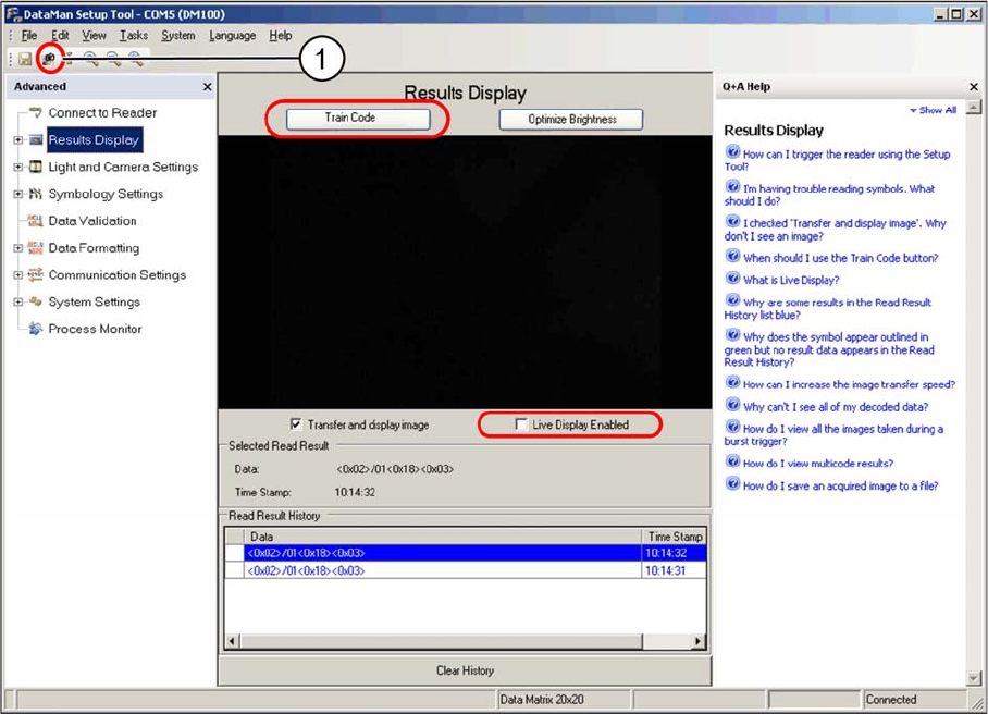
► Change over to the Results Display view.
Results display view - manual trigger
► Position the code in the scan window between the two green luminous markings.
► Click on the Trigger button (1), to manually trigger the image recording.
► Use the image shown and the data string to check whether the code has been read properly.
If successfully read, a green frame will appear around the code.
► Enable the Live Display enabled option, if required.
This makes it easier to position the code in the scan window. However, image assessment is not
performed.
The code should appear vertically positioned, roughly in the center of the image. You may need to adjust
the Y position of the scanner by a few millimeters.
If the scanner is unable to read the code, due to a mirrored PCB surface, adjust the angle of the scanner
in its holder.
The data string transmitted to the conveyor control is shown underneath the image.
Setting up and Commissioning
2D PCB Barcode Scanner Configuring the PCB Barcode Scanner
PCB Barcode LP-Barcode 189
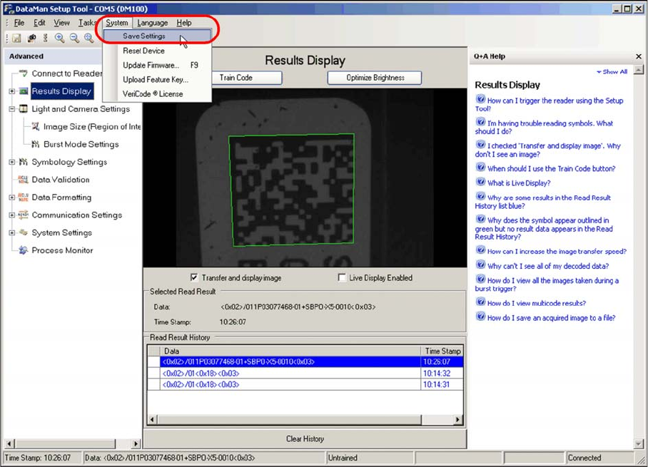
You can also set the scanner to the current code type by clicking on Train code. This achieves the max-
imum operational reliability. The button will then switch over to Untrain code.
If there are several different codes on a board, Train code can be used to select the required code. The
other code types will then be ignored and not scanned.
If you later need to switch over to scanning another code, first cancel the existing setting by clicking on
Untrain code.
Saving settings
Saving settings
► The settings can be permanently saved on the barcode scanner at System --> Save Settings.
For more information, refer to the help function shown on the right.
Setting up and Commissioning
Configuring the PCB Barcode Scanner 2D PCB Barcode Scanner
190 PCB Barcode LP-Barcode
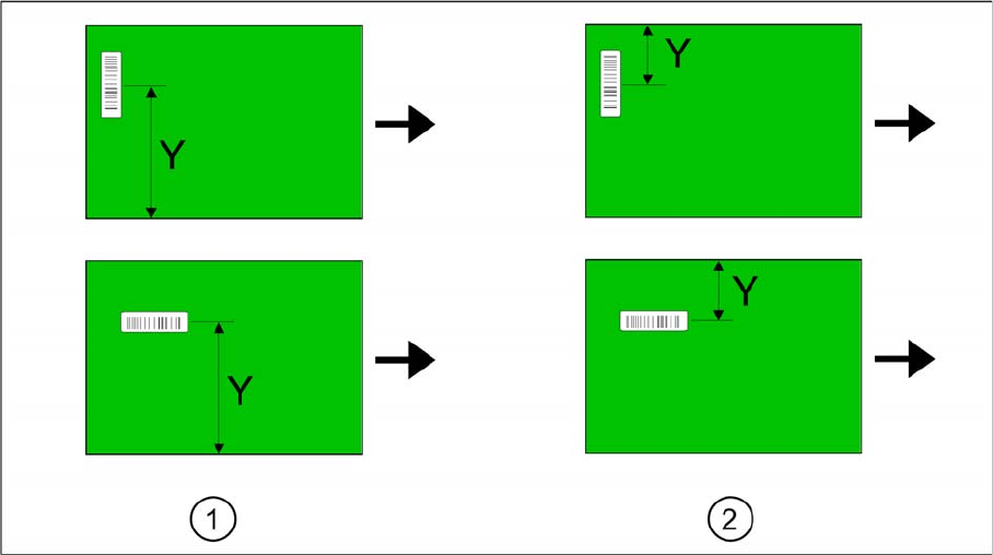
Setting the barcode scanner to the board
The barcode scanner needs to be set to the printed circuit board on initial installation and before each
product change.
Find the Y dimension on the board.
Legend
1. Fixed conveyor side = right
2. Fixed conveyor side = left
The barcode scanner needs to be set to the position of the code on the printed circuit board. A setting
scale is provided on the barcode scanner guide rails, for this purpose.
► Determine the Y dimension on the board i.e. the center of the code to the board edge of the fixed
conveyor side.
► Use the pointer on the scale to set the Y dimension. The required accuracy is approx. +/- 2 mm.