00196625-03_AI_SX12_PCB_Barcode_de_en.pdf - 第138页
Setting up and Commissioning Installing the PCB Barcode Scanner Running the Cables 138 PCB Barcode LP-Barcode 3.2.3.4 Winding and Fixing the Cable See also 3.2.2.3. 1 Parallel to the Direction of Travel, Left [ ➙ 125…
Setting up and Commissioning
Installing the 2D PCB Barcode Scanner Installing the PCB Barcode Scanner
PCB Barcode LP-Barcode 137
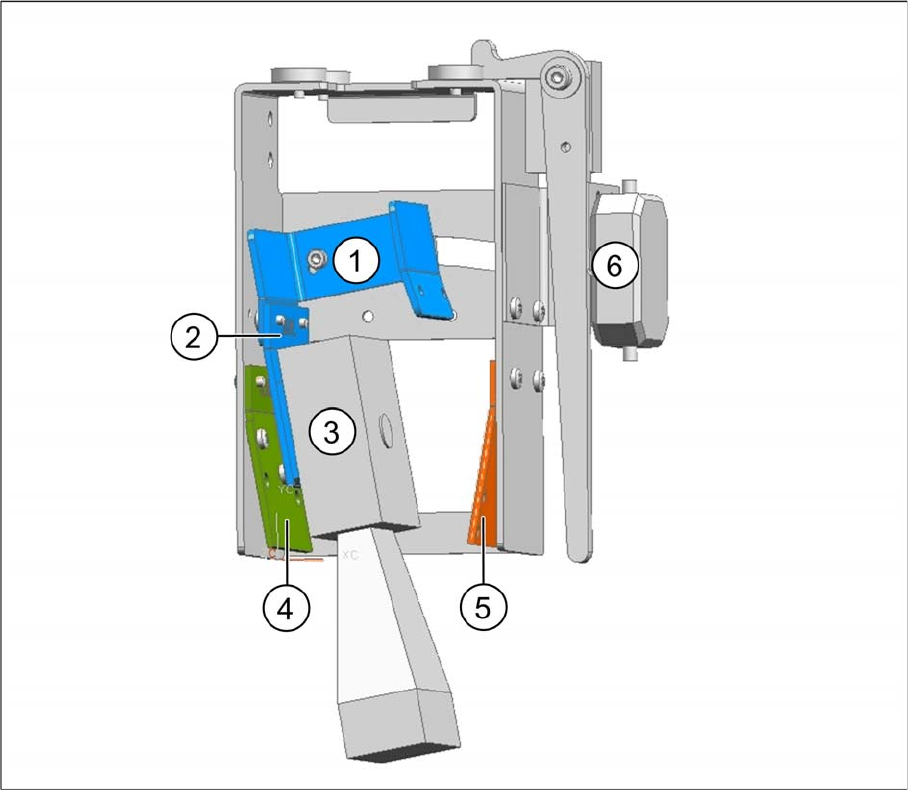
2D barcode scanner parallel to the direction of travel, installation on left
Legend
► Wind up the cable and fix it into place (see "3.2.3.4 Winding and Fixing the Cable" [ ➙ 138]).
1 Fixing bracket 2 2D BC holding bracket left
3 Barcode scanner 4 1D BC holding bracket right and left
5 2D BC holding bracket left 6 Position for connector
Setting up and Commissioning
Installing the PCB Barcode Scanner Running the Cables
138 PCB Barcode LP-Barcode
3.2.3.4 Winding and Fixing the Cable
See also
3.2.2.3.1 Parallel to the Direction of Travel, Left [ ➙ 125]
3.2.4 Running the Cables
The 1D barcode scanner and 2D barcode scanner each have their own sets of cables. Take care never
to confuse these cable sets e.g. during conversion work.
The principle for running the 1D and 2D cable sets is the same. Arrange the cables and the mounting
frame on a suitable work surface.
Cable set for 2D barcode scanner [03075946-xx]
The cable set is contained in the "Electrics Assembly Kit for 2D PCB Barcode Scanners", item no.
[00519889-xx].
Cable set for 1D PCB barcode scanner [03074225-xx]
The cable set is contained in the "Electrics Assembly Kit for 1D PCB Barcode Scanners", item no.
[00519890-xx].
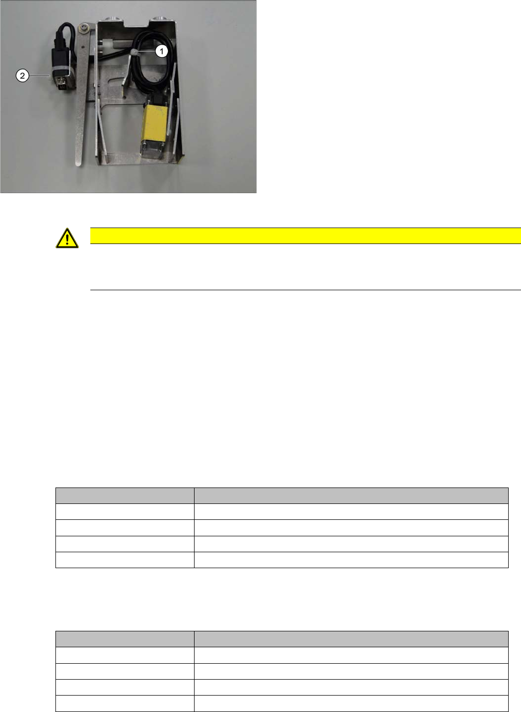
Example: 2D PCB barcode scanner at cross angled cable
Legend
1. Cable ties
2. Cable ties
► Run the cable for the SUB-D connector in loops and
fix it with a cable tie to the position (1) on the holder.
► Guide the SUB-D connector under the holder and out
and then fix it into place with a cable tie (2).
Pull the cable tie through the two drilled holes provid-
ed. When using a 1D PCB barcode scanner, you
need to fit an intermediate adapter (gender changer)
to the SUB-D connector. This adapter prevents the
1D PCB barcode scanner from being accidentally at-
tached to the cable set for the 2D scanner.
CAUTION
Do not get the sets of cables confused with one another.
Make sure that the 1D PCB barcode scanner is not connected to the cable set for the 2D scan-
ner. This would damage the 1D PCB barcode scanner!
Conveyor lane Required cable
Conveyor lane 1 top Cable, barcode scanner DM100 lane 1 top [03079389-xx]
Conveyor lane 2 top Cable, barcode scanner DM100 lane 2 top [03079391-xx]
Conveyor lane 1 bottom Cable, barcode scanner DM100 lane 1 bottom [03075944-xx]
Conveyor lane 2 bottom Cable, barcode scanner DM100 lane 2 bottom [03079390-xx]
Conveyor lane Required cable
Conveyor lane 1 top Cable BC scanner DS1500 lane 1 top [03079352-xx]
Conveyor lane 2 top Cable BC scanner DS1500 lane 2 top [03079354-xx]
Conveyor lane 1 bottom Cable BC scanner DS1500 lane 1 bottom [03074066-xx]
Conveyor lane 2 bottom Cable BC scanner DS1500 lane 2 bottom [03079353-xx]
Setting up and Commissioning
Running the Cables Installing the PCB Barcode Scanner
PCB Barcode LP-Barcode 139
3.2.4.1 Holders in the Mounting Frame
3.2.4.2 Marking the Cable Length to the SUB-D Connector
3.2.4.3 Inserting and Running the Cables
For details of the cables used for each barcode reader type and conveyor lane, see "3.2.4 Running the
Cables" [ ➙ 138].
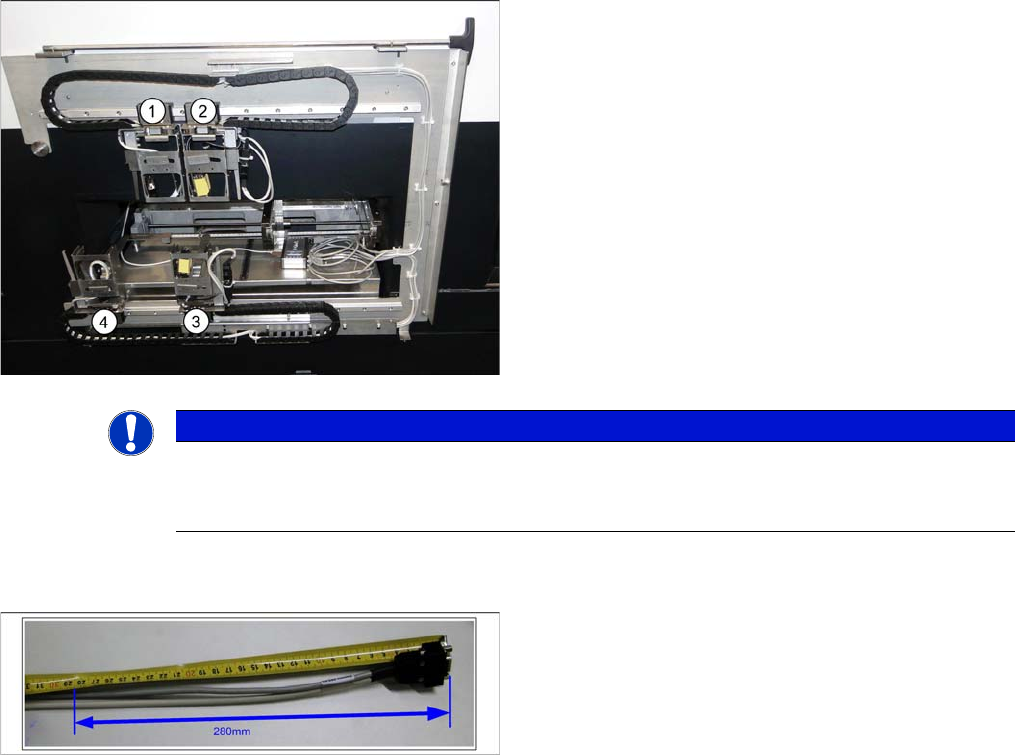
Legend
1. Conveyor lane 2 top
2. Conveyor lane 1 top
3. Conveyor lane 1 bottom
4. Conveyor lane 2 bottom
► Check the amount of chain links and shorten each to
25 chain links per conveyor lane.
You must be able to freely move the barcode holders
along the entire area. The trailing cables must never be
tensioned or jolted.
NOTICE
End stopper
Before fitting the mounting frame onto the machine, make sure that that the ends of the guide
rail each have a screw with disk as end stopper, otherwise the guide trolley could slip off the rail.
► Mark the cable at 280 mm from the SUB-D connector.
This length is required for the distance from the exit
from the mounting frame to the connection on the
PCB barcode (see photos to run the cable in the dif-
ferent conveyor lanes).