00196625-03_AI_SX12_PCB_Barcode_de_en.pdf - 第187页
Setting up and Commissioning 2D PCB Barcode Scanner Configuring the PCB Barcode Scanner PCB Barcode LP-Barcode 187 "Light and Camera Settings" view ► Set the Trigger-Type to Burst (e xternal) . ► Go to Burst le…
Setting up and Commissioning
Configuring the PCB Barcode Scanner 2D PCB Barcode Scanner
186 PCB Barcode LP-Barcode
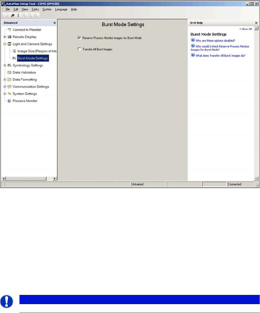
"Burst Mode Settings" view
The Cognex 2D scanner is a camera-based system, which records trigger-controlled individual images
and then searches through these for the codes contained using special algorithms.
The Burst Mode function of the scanner describes the process of taking and storing a large number of
images within a certain period. The images are then evaluated in sequence and the first code found is
transmitted.
► Enable the Reserve Process Monitor images for Burst Mode option. This provides storage capacity
for 22 image recordings, instead of just 16.
The function Transfer All Burst Images can be helpful for detecting errors. This transfers all images re-
corded during one burst to the Windows SW and not just the first image in which a code is found. How-
ever, due to the length of time taken for evaluation and transmission, this function should not be enabled
for normal operations.
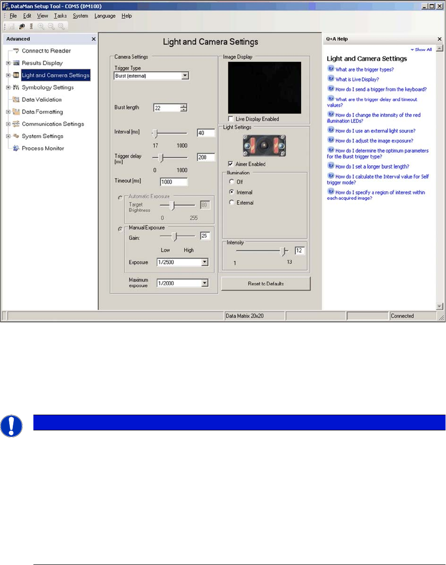
► Switch over to the Light and Camera Settings view.
General settings can be defined there, such as trigger delay, exposure and intensity.
NOTICE
This field should be disabled after the settings and tests have been completed.
Setting up and Commissioning
2D PCB Barcode Scanner Configuring the PCB Barcode Scanner
PCB Barcode LP-Barcode 187
"Light and Camera Settings" view
► Set the Trigger-Type to Burst (external).
► Go to Burst length and enter a value of 22 for the maximum number of images to be recorded.
► Go to Interval and specify the time interval between the individual images.
A practical starting value for the interval is 40 ms and an advisable time range is approx. 30...80 ms.
If the code is always in the middle or rear part of the board, the start of image recording after the trigger
signal ( = when the conveyor switches on) can be delayed using the setting Trigger delay, so that the
image recording only begins when the code is just in front of the reading window. As a result, the image
memory available (burst length) is used specifically for the area of the board which contains the code.
This means that, even on longer boards, a longer code can be read than would be possible without the
Trigger Delay function. The default value is 200 ms.
► Go to Maximum exposure and enter a maximum exposure time of 1/2000 s.
A longer exposure leads to fuzziness, caused by the speed at which the board is inserted. Codes
with small cells (e.g. 10 mil) require an even lower maximum exposure.
NOTICE
The reader records 22 images in burst mode after receiving the trigger signal (= burst length)
with the image rate 1/interval time. A longer interval time enables you to search for the code
over a greater area on the board currently inserted. however, the overlapping of two consecu-
tive images is reduced so that only codes with smaller dimensions can be read. For reliable
reading, you need to make sure that the complete code is present in at least two images. This
means that larger codes require a greater overlapping of the individual images, which can only
be achieved during constant conveyor speed by setting a shorter interval time between the in-
dividual images.
Setting the interval time is always a compromise between the required scan length on the board
and the maximum code size which can be read.
Setting up and Commissioning
Configuring the PCB Barcode Scanner 2D PCB Barcode Scanner
188 PCB Barcode LP-Barcode
► Go to Timeout and enter the maximum time after which searching should be terminated, if the sys-
tem is unable to find a code in a single image.
The time required to find a code depends greatly on the quality of the code or image recorded and
on the amount of interfering structures in the image (e.g. circuit paths on the board). The default
Timeout value is 100 ms.
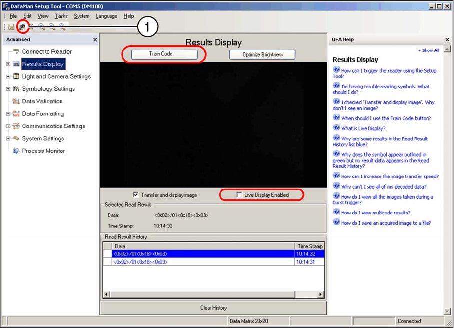
Testing the settings
You can now check the settings in the Result Display view. The scanner will execute the number of im-
ages specified in the Burst Mode Settings and will then show its results at the top and bottom of the win-
dow.
Image recording is terminated prematurely as soon as a code is found in the image.
► Change over to the Results Display view.
Results display view - manual trigger
► Position the code in the scan window between the two green luminous markings.
► Click on the Trigger button (1), to manually trigger the image recording.
► Use the image shown and the data string to check whether the code has been read properly.
If successfully read, a green frame will appear around the code.
► Enable the Live Display enabled option, if required.
This makes it easier to position the code in the scan window. However, image assessment is not
performed.
The code should appear vertically positioned, roughly in the center of the image. You may need to adjust
the Y position of the scanner by a few millimeters.
If the scanner is unable to read the code, due to a mirrored PCB surface, adjust the angle of the scanner
in its holder.
The data string transmitted to the conveyor control is shown underneath the image.