00196625-03_AI_SX12_PCB_Barcode_de_en.pdf - 第130页
Setting up and Commissioning Installing the PCB Barcode Scanner Installing the 2D PCB Barcode Scanner 130 PCB Barcode LP-Barcode 3.2.2.4 1D PCB Barcode Scanner - Attaching a Laser Warning Label Attach the supplied warnin…
Setting up and Commissioning
Installing the 1D PCB Barcode Scanner Installing the PCB Barcode Scanner
PCB Barcode LP-Barcode 129
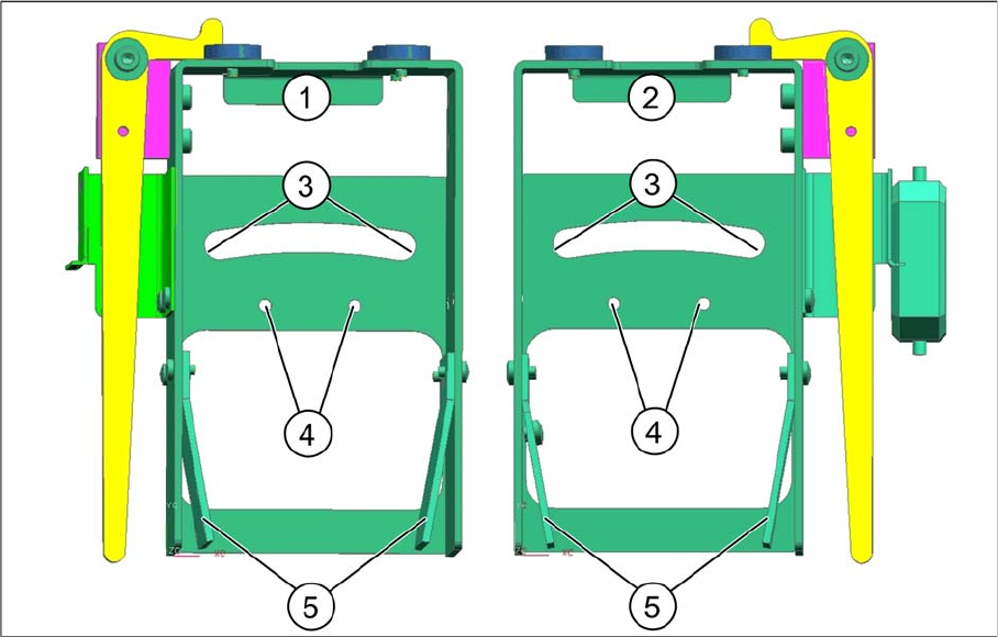
Fitting the fixing bracket into the holder
Installation position in the holder
Legend
► Position the fixing bracket from above onto the arched aperture (3) and the arched clamping piece
from below, against the aperture and then screw both together from above.
By moving the fixing bracket along the arched aperture, you can adjust the angle from approx. 5° to
15°. Fixing the bracket in the center of the aperture (3) achieves approx. 10°.
► Fasten unused BC holding brackets to the positions shown at (5).
► Wind up the cable and fix it into place (see "3.2.3.4 Winding and Fixing the Cable" [ ➙ 138]).
See also
3.2.2.3.1 Parallel to the Direction of Travel, Left [ ➙ 125]
1 Holder for BC scanner, mirrored [03078730-
xx]
2 Holder for BC scanner [03083937-xx]
3 Arched aperture with mounting position for fix-
ing bracket and clamping piece, BC scanner
right / left
4 Mounting position for BC scanner, cross an-
gles
5 Park positions for unused BC holding brackets
Setting up and Commissioning
Installing the PCB Barcode Scanner Installing the 2D PCB Barcode Scanner
130 PCB Barcode LP-Barcode
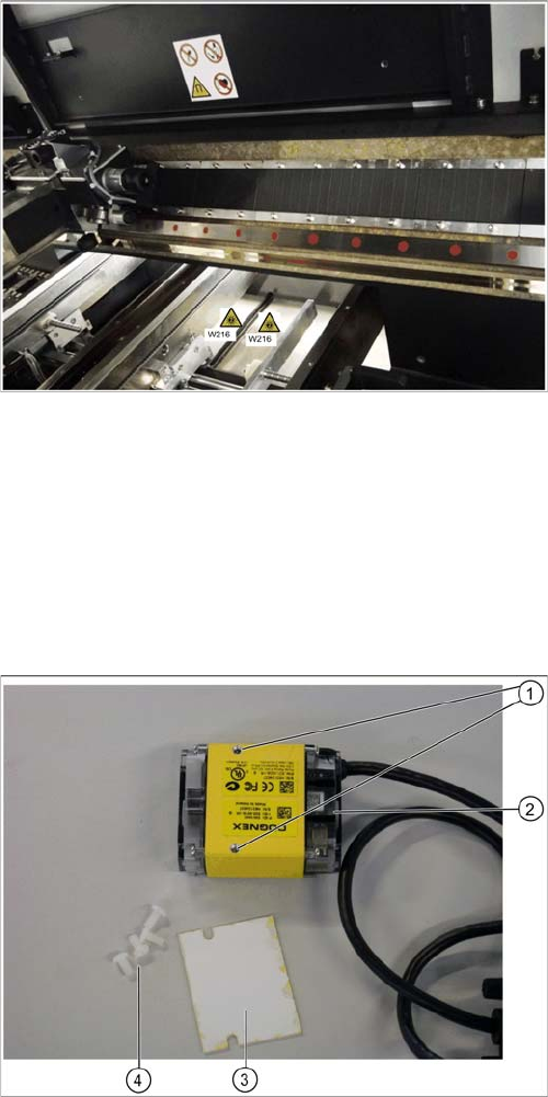
3.2.2.4 1D PCB Barcode Scanner - Attaching a Laser Warning Label
Attach the supplied warning label W216 "Laser class 2" item no. 03009347-01 to the machine and hold-
er, accordingly. Two labels are provided for each barcode scanner.
► Attach a warning label next to the main switch.
► Attach a warning label to the center of the cover over the input conveyor.
Continue with section "3.2.4 Running the Cables" [ ➙ 138].
3.2.3 Installing the 2D PCB Barcode Scanner
3.2.3.1 2D PCB Scanner - Parts
► Unpack the 2D barcode scanner.
Warning labels on the inside of the machine
► Attach additional warning labels inside the machine,
on the covers of the conveyor controls.
2D barcode scanner - parts
Legend
1. Drilled holes for fixing the insulating plate
2. 2D barcode scanner
3. Plastic screws
4. Insulating screws
Setting up and Commissioning
Installing the 2D PCB Barcode Scanner Installing the PCB Barcode Scanner
PCB Barcode LP-Barcode 131
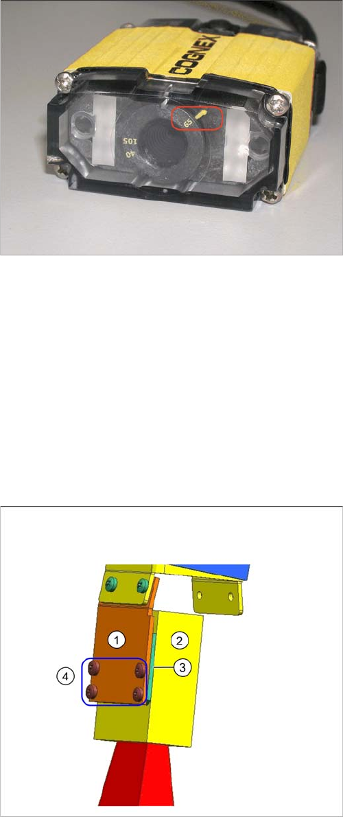
Checking the lens setting
3.2.3.2 Fixing the 2D PCB Barcode Scanner to the Holding Bracket
The following holding rackets are supplied:
▪ 1D BC holding bracket right and left [03084154-xx]
▪ 2D BC holding bracket left [03083915-xx]
▪ 2D BC holding bracket right [03084153-xx]
According to your required installation position, use either the 2D BC holding bracket left [03083915-xx]
or the 2D BC holding bracket right [03084153-xx].
Unused holding brackets are fixed into the holder to ensure that are not lost (see position 5 in "3.2.1 In-
stallation Position in the Holder" [ ➙ 122]).
Lens setting 65
► Check whether the distance setting of the lens is set
to 65.
Barcode scanner fixed to holding bracket - right shown as
example
Legend
1. 2D BC holding bracket right [0308953-xx]
2. 2D barcode scanner
3. Insulating plate
4. Fastening screws
► Place the insulating plate (3) between the 2D barcode
scanner (2) and the holding bracket (1).
► Screw the three parts into place with the four insulat-
ing screws (4) provided.
► The fixture on the holding bracket left is the same.