00196625-03_AI_SX12_PCB_Barcode_de_en.pdf - 第157页
Setting up and Commissioning Connecting the Barcode Scanner to the SIPLACE SX Installing the PCB Barcode Scanner PCB Barcode LP-Barcode 157 Running the USB cable from the hub to the box PC ► Connect the USB cable to the …
Setting up and Commissioning
Installing the PCB Barcode Scanner Connecting the Barcode Scanner to the SIPLACE SX
156 PCB Barcode LP-Barcode
Fitting the cover and hub
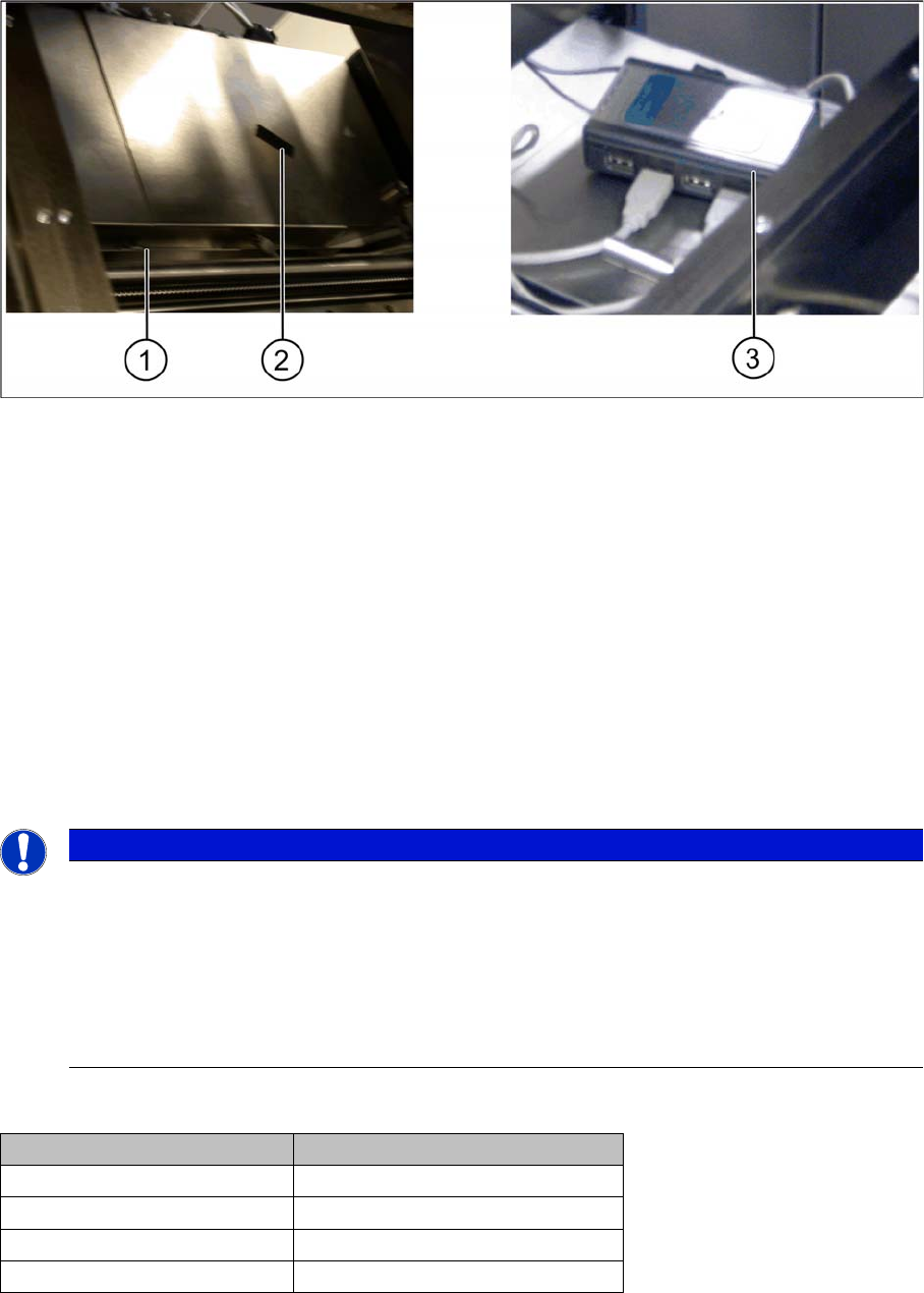
Conveyor control 1 and 2 – cover fitted and USB hub fixed
Legend
1. Nib of cover
2. Hook and loop fastening tape
3. USB hub fixed
► Refit the conveyor control cover(s). Fit the nib (1) under the screw and then fix the covers(s) into
place with the screw.
► Fix the USB hub on one of the two conveyor controls with the help of the hook and loop fastening
tape (2) provided.
► Connect the connection cable for the USB hub to connection X9 of the USB hub.
► Connect the relevant USB cable for the installed barcode scanner(s) to the respective USB hub con-
nection.
Connections and conveyor lanes
NOTICE
Assigning the USB connections in the setup tool of the barcode scanner software
During barcode scanner configuration, the setup tool assigns each scanner connected for the
first time a virtual COM port, which is kept for future use. As the setup tool can only ever estab-
lish a connection to one scanner at a time, we recommend that - on initial installation - you con-
nect just one scanner to the USB hub and let the setup tool then allocate a virtual COM port
and COM number to this. See "3.3.2.1.2 Configuring the Barcode Scanner Software" [ ➙ 178].
► Repeat this procedure for all barcode scanners to be connected.
Conveyor lane Connections on the USB hub
Conveyor lane 1 top X85_2 on X2
Conveyor lane 2 top X85_4 on X4
Conveyor lane 1 bottom X85_1 on X1
Conveyor lane 2 bottom X85_3 on X3
Setting up and Commissioning
Connecting the Barcode Scanner to the SIPLACE SX Installing the PCB Barcode Scanner
PCB Barcode LP-Barcode 157
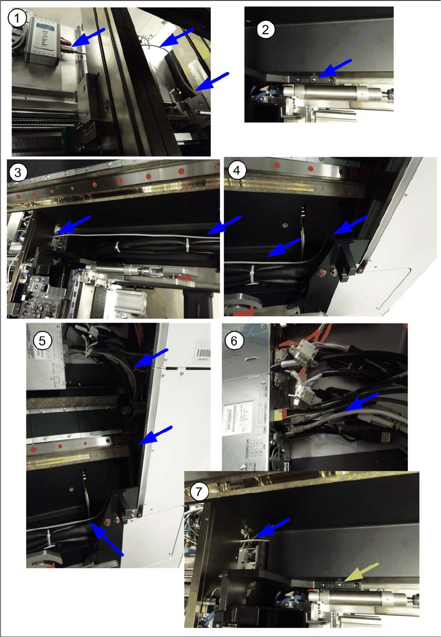
Running the USB cable from the hub to the box PC
► Connect the USB cable to the relevant connection on the hub and run the cable over the conveyor
control cover towards the Box PC (1).

Setting up and Commissioning
Installing the PCB Barcode Scanner Fitting the Ruler
158 PCB Barcode LP-Barcode
► Run the cable under the conveyor side and through the cable duct to the box PC (2 to 4). Make sure
that the cable is not in the hazard area of the gantry.
► Use cable ties to fix the cable to the other cables already present.
► Connect the cable to the unoccupied USB port on the box PC (5).
► Fit the cover on the cable duct (6).
See also
3.3.2 2D PCB Barcode Scanner [ ➙ 177]
3.2.8 Fitting the Ruler
You can measure the Y position of the PCB barcode scanner with the help of the ruler and pointer. The
zero point of the ruler corresponds to the position of the fixed conveyor side. A separate ruler is supplied
on its own support plate for the top and bottom installation positions at which the PCB barcode scanner
can be fitted.
The ruler position on its support plate can be changed according to the position of the fixed side (align-
ment from left to right or from right to left possible).
CAUTION
Pay attention to the conveyor version
► The pointer version used will depend on the conveyor.
Use the long pointer [03073262-xx] at V1-conveyors.
Use the short pointer [03095905-xx] at V2-conveyors.
► The position of the ruler is represented by the example of a V1-conveyor.
At V2-conveyors the position of the ruler differs from the pictures.