00196625-03_AI_SX12_PCB_Barcode_de_en.pdf - 第151页
Setting up and Commissioning Connecting the Barcode Scanner to the SIPLACE SX Installing the PCB Barcode Scanner PCB Barcode LP-Barcode 151 3.2.7.1 Connecting the 1D PCB Barcode Scanner Option board on conveyor lane 1 w …
Setting up and Commissioning
Installing the PCB Barcode Scanner Connecting the Barcode Scanner to the SIPLACE SX
150 PCB Barcode LP-Barcode
3.2.7 Connecting the Barcode Scanner to the SIPLACE SX
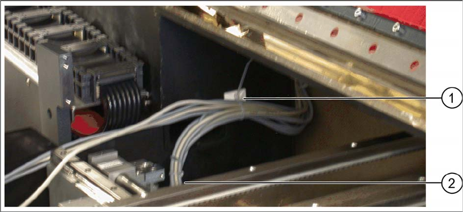
Cable clamp on the machine base
► Pull the barcode scanner cable into the machine and fix it into place on the machine base with the
cable clamp (1).
► Remove the plastic bag.
► Run the cable through the recess in the housing (2) and on towards the conveyor control.
Setting up and Commissioning
Connecting the Barcode Scanner to the SIPLACE SX Installing the PCB Barcode Scanner
PCB Barcode LP-Barcode 151
3.2.7.1 Connecting the 1D PCB Barcode Scanner
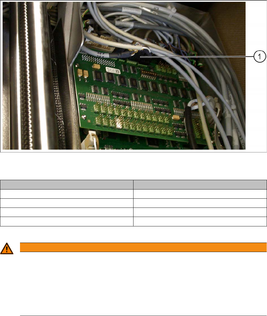
Option board on conveyor lane 1 with connected barcode scanner cables
► Connect each barcode scanner according to the wiring plan on the option board (1):
You can use the diagram on the inside of the conveyor control cover for help.
Conveyor lane Connections on relevant option board
Conveyor lane 1 top X82 on X82 and X84 on X84
Conveyor lane 2 top X82 on X82 and X84 on X84
Conveyor lane 1 bottom X81 on X81 and X83 on X83
Conveyor lane 2 bottom X81 on X81 and X83 on X83
WARNING
Handling the cable
Cables may only be connected to or disconnected from the machine when currentless.
The connector encoding informs the conveyor control that a scanner is to be used at the rele-
vant installation position. If the scanner is missing, an error message will be issued.
► Please note that scanner cables may only be connected to the option board if the corre-
sponding scanner has been fitted.
► Take care that the cables do not get into the hazard area of the machine.
Setting up and Commissioning
Installing the PCB Barcode Scanner Connecting the Barcode Scanner to the SIPLACE SX
152 PCB Barcode LP-Barcode
Fitting the cover and converter
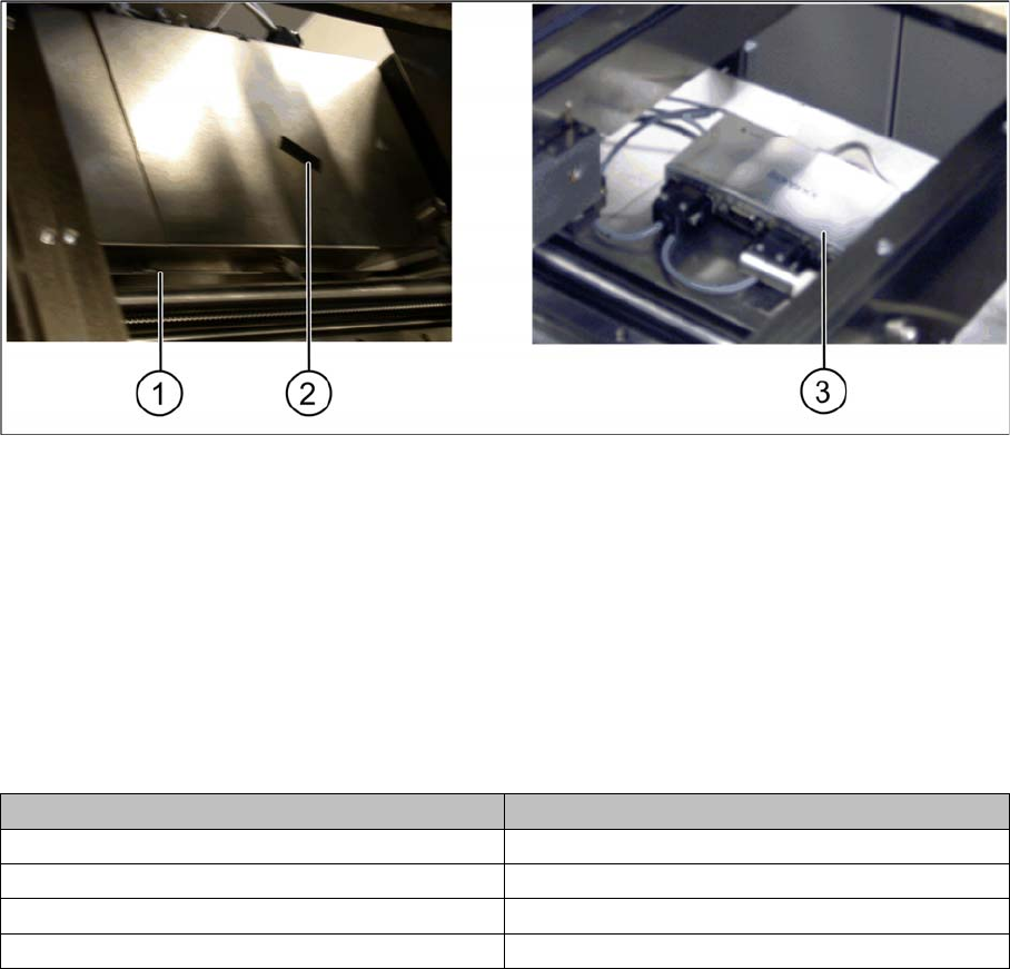
Conveyor control 1 and 2 – cover fitted and RS232/USB converter fixed
► Refit the conveyor control cover(s). Fit the nib (1) under the screw and then fix the covers(s) into
place with the screw.
► Fix the RS232/USB converter on one of the two conveyor controls with the help of the hook and loop
fastening tape (2) provided.
Connections and conveyor lanes
1 Nib of cover 2 Hook and loop fastening tape
3 RS232/USB converter, fixed
Conveyor lane Connections to the RS232/USB converter
Conveyor lane 1 top X85_2 on X2
Conveyor lane 2 top X85_4 on X4
Conveyor lane 1 bottom X85_1 on X1
Conveyor lane 2 bottom X85_3 on X3