00196625-03_AI_SX12_PCB_Barcode_de_en.pdf - 第140页
Setting up and Commissioning Installing the PCB Barcode Scanner Running the Cables 140 PCB Barcode LP-Barcode Inserting the Cables int o the Trailing Cable - Example See also 3.2.4 Running the Cables [ ➙ 138] Inserti…
Setting up and Commissioning
Running the Cables Installing the PCB Barcode Scanner
PCB Barcode LP-Barcode 139
3.2.4.1 Holders in the Mounting Frame
3.2.4.2 Marking the Cable Length to the SUB-D Connector
3.2.4.3 Inserting and Running the Cables
For details of the cables used for each barcode reader type and conveyor lane, see "3.2.4 Running the
Cables" [ ➙ 138].
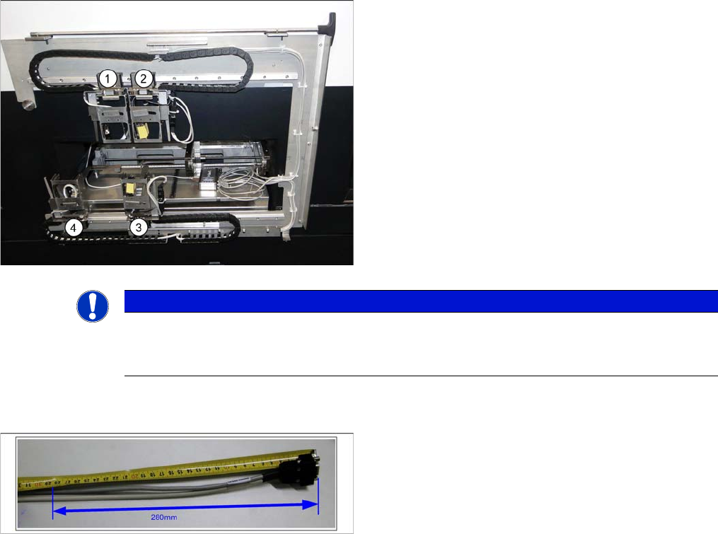
Legend
1. Conveyor lane 2 top
2. Conveyor lane 1 top
3. Conveyor lane 1 bottom
4. Conveyor lane 2 bottom
► Check the amount of chain links and shorten each to
25 chain links per conveyor lane.
You must be able to freely move the barcode holders
along the entire area. The trailing cables must never be
tensioned or jolted.
NOTICE
End stopper
Before fitting the mounting frame onto the machine, make sure that that the ends of the guide
rail each have a screw with disk as end stopper, otherwise the guide trolley could slip off the rail.
► Mark the cable at 280 mm from the SUB-D connector.
This length is required for the distance from the exit
from the mounting frame to the connection on the
PCB barcode (see photos to run the cable in the dif-
ferent conveyor lanes).
Setting up and Commissioning
Installing the PCB Barcode Scanner Running the Cables
140 PCB Barcode LP-Barcode
Inserting the Cables into the Trailing Cable - Example
See also
3.2.4 Running the Cables [ ➙ 138]
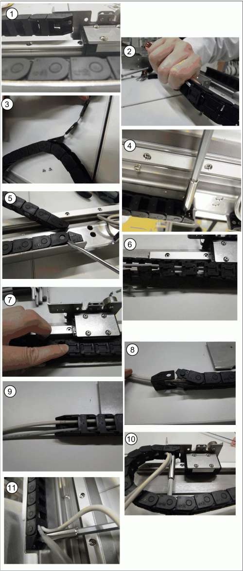
Inserting the cables into the trailing cable - scanner on
conveyor lane 2, bottom
► Release the trailing cable from the PCB barcode re-
ceptacle (1).
► Loosen the fixture clips on the trailing cable by taking
a screwdriver to the first chain link and carefully eas-
ing out (levering) the clip (2).
► Now pull the other clips off the chain links (3).
► Take the trailing cable off the holder for the PCB bar-
code assembly plate (4).
► Lever the end piece of the trailing cable off by gently
pushing it apart (5).
► Place the cable into the trailing cable (6).
► Gently press the clips back onto the trailing cable so
that these engage audibly. Pay attention to the orien-
tation of the trailing cable (7).
► Push apart the end piece of the trailing cable to rein-
sert it (8 and 9).
► Fix the end of the chain back onto the PCB barcode
receptacle (10).
► Fix the trailing cable back onto the PCB assembly
plate holder (11).
Setting up and Commissioning
Running the Cables Installing the PCB Barcode Scanner
PCB Barcode LP-Barcode 141
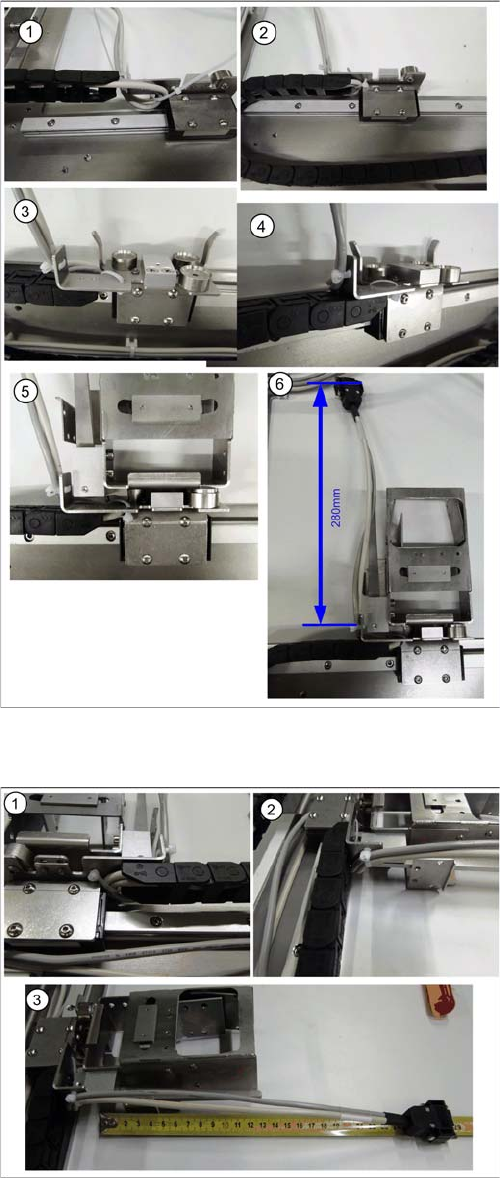
Holder on Conveyor Lane 1 Top - Running Cables
Holder on Conveyor Lane 1 Bottom - Running Cables
► Run the cable to the receptacle for the holder as
shown in diagrams (1 to 6).
► Run the cable between the receptacle for the holder
and the guide rails and fix it into place.
► Fix the cable into place with the two cable ties and the
receptacle for the holder, so that the holder is posi-
tioned level on the magnets, when inserted.
► Cut any excess cable tie. The cables or cable ties
must never protrude beyond the receptacle, other-
wise the mounting frame will not fit when pushed into
the machine installation point (backpack).
► Run the cable to the receptacle for the holder as
shown in diagrams (1 to 3).
► Run the cable between the receptacle for the holder
and the guide rails and fix it into place.
► Fix the cable into place with the two cable ties and the
receptacle for the holder, so that the holder is posi-
tioned level on the magnets, when inserted.
► Cut any excess cable tie. The cables or cable ties
must never protrude beyond the receptacle, other-
wise the mounting frame will not fit when pushed into
the machine installation point (backpack).