00196625-03_AI_SX12_PCB_Barcode_de_en.pdf - 第170页
Setting up and Commissioning Configuring the PCB Barcode Scanner 1D PCB Bar code Scanner 170 PCB Barcode LP-Barcode "Edit Configuration" dialog – "Main Int." tab "Edit Configuration" dialog …
Setting up and Commissioning
1D PCB Barcode Scanner Configuring the PCB Barcode Scanner
PCB Barcode LP-Barcode 169
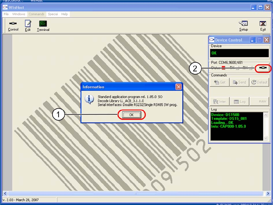
"Device Control" dialog - connected barcode scanner detected
► Confirm the following information message with OK (1).
► Click on the Connect to device (2) button.
The Edit Configuration will be shown.
The entries shown in the individual tabs will be automatically read by the barcode scanner and shown in
the Device Control dialog with the status Configuration received.
Setting up and Commissioning
Configuring the PCB Barcode Scanner 1D PCB Barcode Scanner
170 PCB Barcode LP-Barcode
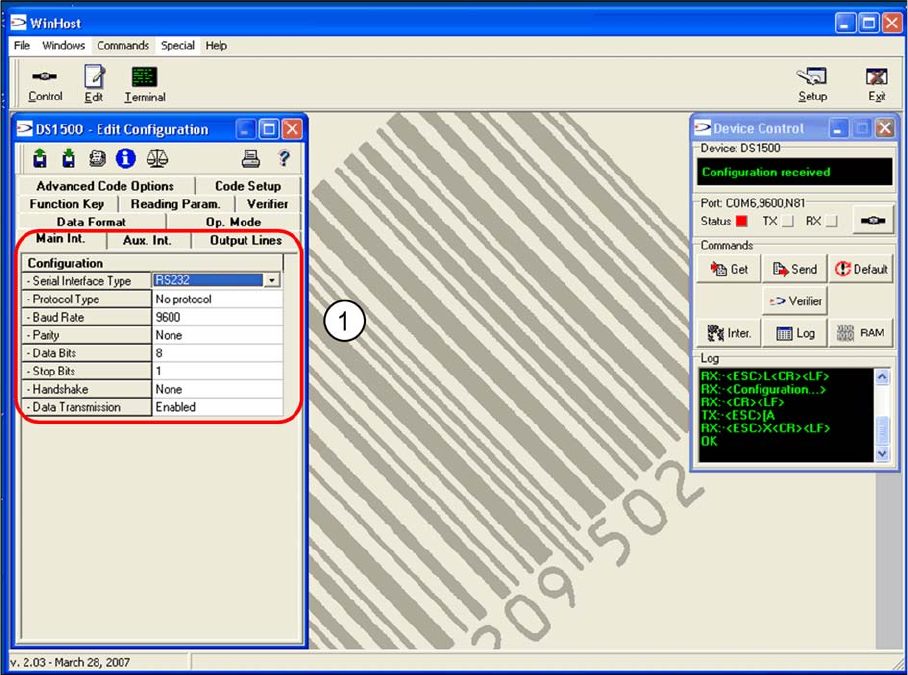
"Edit Configuration" dialog – "Main Int." tab
"Edit Configuration" dialog – "Main Int." tab
The parameters for the MAIN interface, which connects the barcode scanner to the conveyor control (for
transfer of read code data), are set in the Main Int tab.
► Accept the values shown in the screenshot (1).
Setting up and Commissioning
1D PCB Barcode Scanner Configuring the PCB Barcode Scanner
PCB Barcode LP-Barcode 171
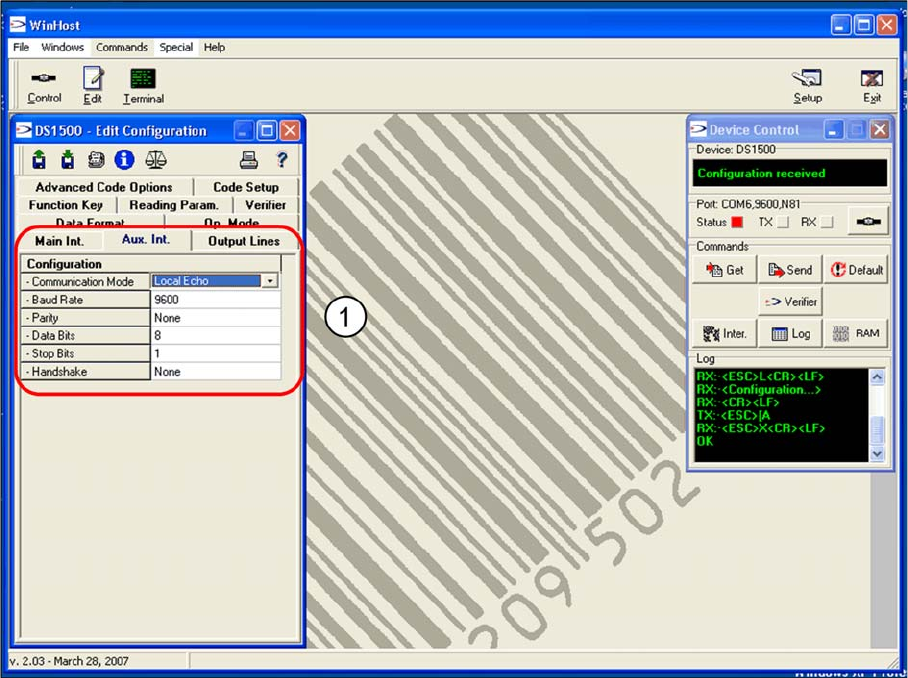
"Edit Configuration" dialog – "Aux Int." tab
"Edit Configuration" dialog – "Aux Int." tab
The parameters for the AUX interface (RS232), which connects the WinHost with the barcode scanner,
are set in the Aux. Int tab, for barcode scanner setup purposes.
► Accept the values shown in the screenshot (1).