00196625-03_AI_SX12_PCB_Barcode_de_en.pdf - 第184页
Setting up and Commissioning Configuring the PCB Barcode Scanner 2D PCB Bar code Scanner 184 PCB Barcode LP-Barcode "System Settings" view ► Select the Outputs tab. ► Define t he settings shown in t he scree ns…
Setting up and Commissioning
2D PCB Barcode Scanner Configuring the PCB Barcode Scanner
PCB Barcode LP-Barcode 183
► Set the parameters shown in the screenshot for the first time.
► Enable the option Enables Multi-Port (RS 232 - Sharing).
► Switch over to the Data Formatting view.
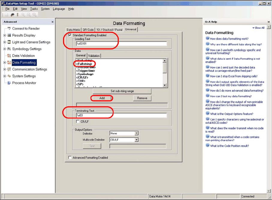
"Data Formatting" view
► Select the Universal tab.
► Define the settings shown in the screenshot.
► Enter the following at Leading Text:
\x02/01
► Enter the following at Terminating Text:
\x03
The Data field shows the part of the data string in the code which is to be sent to the conveyor control.
► Go to the Data field and select the General tab.
► In the selection box, mark the <Full string> line and click on Add.
If required in individual cases, a specific part of the data in the code can be selected or suppressed
here.
The machine can process a maximum data string length of 40 characters. If the data length of the codes
used does not exceed 40 characters, you can select <Full string> to transmit the complete data content.
If a longer code occurs, an error message will be issued at the station (data format barcode, error no. 80).
In order to read a code label which is longer than 40 characters, part of the code must be selected for
transmission, using the <Sub String> option. For example, this could be the characters 1-40.
► Switch over to the System Settings view.
Setting up and Commissioning
Configuring the PCB Barcode Scanner 2D PCB Barcode Scanner
184 PCB Barcode LP-Barcode
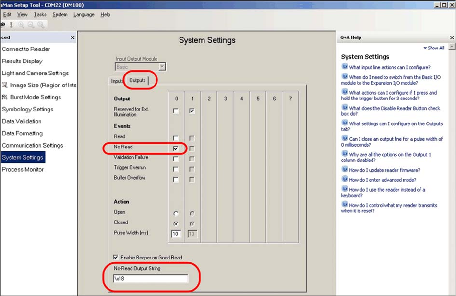
"System Settings" view
► Select the Outputs tab.
► Define the settings shown in the screenshot.
► Enter the following at No-Read Output String:
\x18
After these settings, the barcode scanner is able to provide the machine with the data in the required
formats.
► Switch over to the Symbology Settings view.
The code types and algorithms can be selected there.
Setting up and Commissioning
2D PCB Barcode Scanner Configuring the PCB Barcode Scanner
PCB Barcode LP-Barcode 185
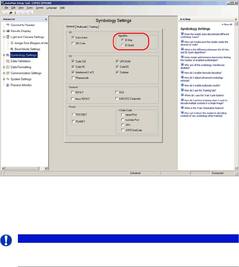
"Symbology Settings" view
► Select the General tab.
► Select the ID Max algorithm.
► Enable the code types used on the board(s). In most cases this will only be Data Matrix.
You can also choose 1D codes here. However, due to the movement of the PCB during scanning, and
the single-image method used by the scanner, 1D barcodes can only be read if they are very small.
► Go to the Light and Camera Settings view and switch to Burst Mode Settings.
NOTICE
If no selection is possible, this means that the scanner has already been programmed to a cer-
tain fixed code (Train Code).
► In this case, switch over to the Results Display dialog and click on Untrain code.