YSD_Users_E.pdf - 第119页
3-6 3 Q & A 2. Handling dispensing errors If the dispensing errors shown in the figure below occur during production, troubleshoot by doing the tasks in the appropriate box in the table. T ypical dispensing errors To…

3-5
3
Q & A
1.4 Other errors
Possible cause and corrective action
The number of coordinate data points resulted in error
Cause There are too many coordinate data points.
Action Check the mount, offset, fiducial and badmark data, and reduce the number of data points.
3-6
3
Q & A
2. Handling dispensing errors
If the dispensing errors shown in the figure below occur during production, troubleshoot by doing the tasks in
the appropriate box in the table.
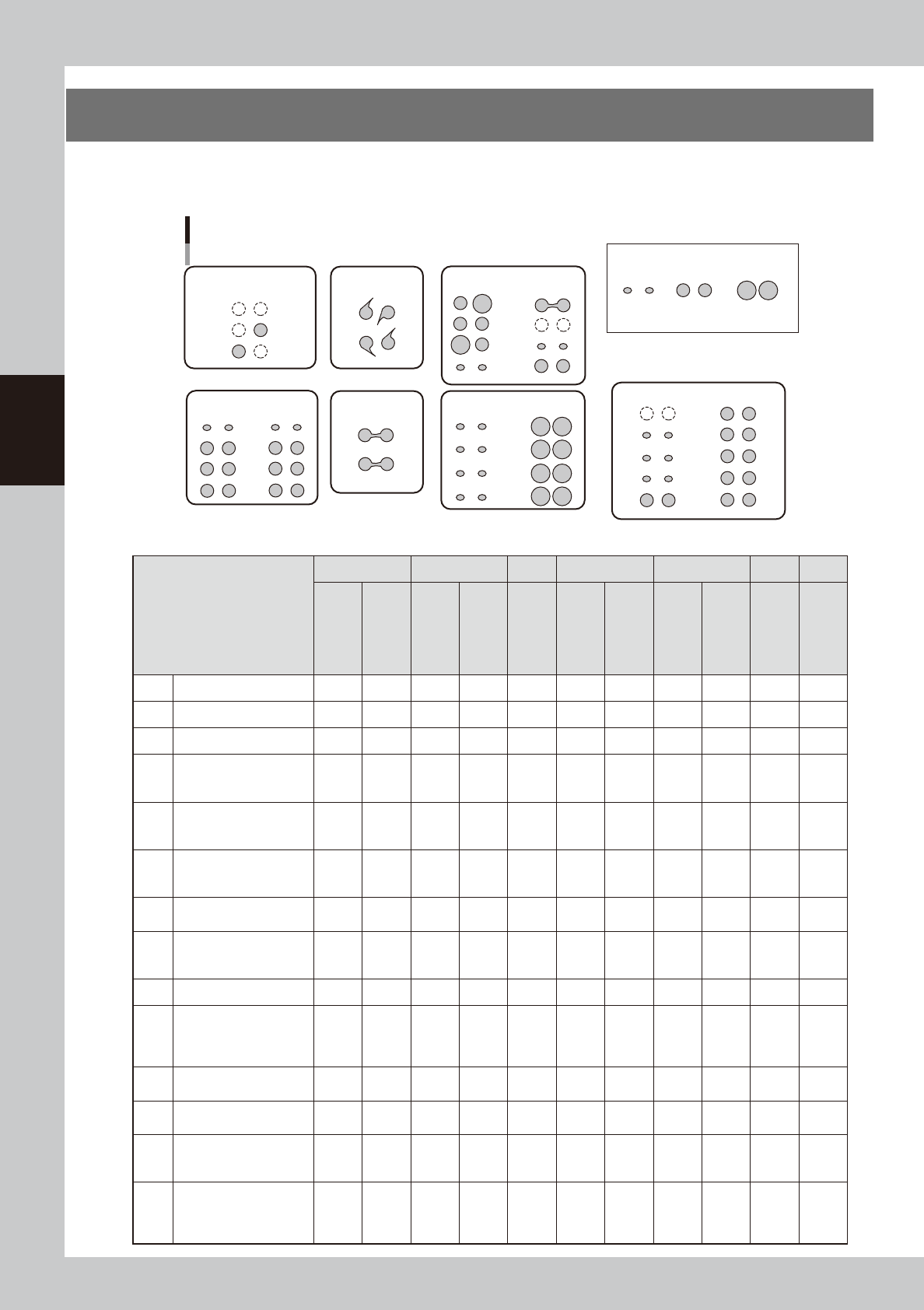
Typical dispensing errors
Too little Standard
[Sample dispensing quantities]
Too much
A: No dispensing or
dispensing only one dot
C: Cobwebbing
D: Bridges
B: Too little dispensing
at initial points
E: Irregular dispensing
F: Overall amount too
small or too large
G: Unstable dispensing after stopping
63300-N7-00
Troubleshooting/
Error description
A B C D E F G
No dispensing
Dispensing only
one dot
Too little
dispensing at
initial points
Too little after
moving long
distance
Cobwebbing
Bridges
(partial)
Bridges
(all)
Irregular
dispensing
(overall)
Irregular
dispensing
(designated
points)
Overall
dispensing
amount too small
or too large
Unstable
dispensing
after stopping
machine
[1] Bleed the nozzle air 2 1 1 2
[2] Clean nozzle 3 2 2 3
[3] Increase back-up pins 4 3 2 2 3 1
[4]
Run dispensing test
to check and adjust
dispensing pressure
1 1 1 1 2
[5]
Increase dispensing
quantity at designated
points
2 1 2
[6]
Add predispensing
immediately before
actual dispensing
3 2 6 3 3
[7]
Check the dispensing
temperature
1 3 2 4 4
[8]
Check the standard
area and predispensing
values
4 3 5
[9] Perform predispensing 1 1
[10]
Check remaining
quantity
* Readjust low-liquid
sensor
5 5 4
[11]
Change the dispensing
sequence
3 5 4 4
[12]
Use the spare
correction table
4
[13]
Set the minimum &
maximum correction
values
6
[14]
Make overall
adjustments with
the nozzle data &
coefficients
5 7 5
3-7
3
Q & A
Troubleshooting Description
[1] Bleed the nozzle air
Continue until a fully dispensed bond is obtained with no liquid cutoff. (Sporadic cutoff during
dispensing is usually caused by bubbles.)
[2] Clean the nozzle
• Immerse the nozzle in acetone or other solvents, and use a needle to remove bond adhering on
the paths.
• Clean the nozzle while being careful not to damage the paths since there is a difference
between the left and right nozzles.
(For more details, see “1.2 Cleaning the nozzle” in Chapter 2 of the maintenance manual.)
[3] Increase the back-up pins
Place pins as many as possible to prevent the downward warping of board which may be caused
by syringe nozzles when they make contact with the board.
[4]
Run a dispensing test
to check and adjust the
dispensing pressure
• Manually adjust the pressure around ±20% to reduce the change in the dispensing amount. • •
This increases accuracy of the offset value.
• Reset the offset value after running the dispensing test.
(For more details, see “2. Dispensing test function” in Chapter 4.)
[5]
Increase the dispensing
amount at designated
points
• On the [Board]-[Dot Dispense] screen, change the liquid quantity at required points.
• To change the overall liquid quantity for applicable parts, correct the parts information and re-
perform dispensing.
[6]
Add predispensing
immediately before actual
dispensing.
Add by direct manual input. (For more details, see the section “If not dispensing” in “4.1 Adding
dispensing” in Chapter 7.)
[7]
Check the dispensing
temperature
Inquire to bond manufacturer about the correct temperature.
[8]
Check the standard area
and predispensing values
Check if the predispensing liquid quantity and the liquid quantity for standard area are the same.
The difference between the actual dispensing area and the standard dispensing area is found
from the offset type (map). So if these differ, the predicted area cannot be obtained.
(For more details, see “3.18 Checking that each setting is consistent” in Chapter 4.)
[9] Perform predispensing.
• Perform predispensing for each board and check the results.
(For details, see “Predispensing interval setting” in Chapter 3.)
• Make the following settings for predispensing.
On the [Board] – [Board] tab, set “T: Refresh Dispense” to “Time”.
In the VmSpec window that appears with the [Machine] button, open “Dot Station” and set “Ref.
Timer A” to 240 and “Dot Number” to 10.
*If only standard nozzles are used, add the following settings:
Change “Dot Matrix - Pitch” from 6.000 to 4.00, and “Dot Matrix - Amount” from 6 to 10.
(For details, see “5.1.1 Setting the automatic predispensing function” in Chapter 4.)
[10]
Check the remaining
amount of liquid.
*Readjust the low-liquid
sensor.
The low-liquid sensor has a response range, so always make sure the detected values by turning
each syringe.
(Liquid remains: Position where the value is highest. / No liquid remains: Position where the
value is lowest.)
(For more details, see “4.1.1 Adjusting the low-liquid sensor” in Chapter 2.)
[11]
Check the dispensing
sequence.
Change the dispensing sequence. (For more details, see “6.2 Editing the dispensing sequence”
in Chapter 4.)
[12]
Use the spare correction
table.
• All nozzles: In the VmSpec window, open “Spare correction table” and make settings for each
nozzle.
• Only first point: In the VmSpec window, open “Nozzle Data” and enter the value (timer) in “Spare
liquid amount”.
[13]
Set the minimum and
maximum correction
values.
In the VmSpec window, open “Dot Station” and set “DotDsp Check” under “Position” to “Use”.
Also open “Dispense Correction” and enter the “Minimum Correction” and “Maximum Correction”
values.
[14]
Make overall adjustment
using “Nozzle Data -
Coefficient”.
In the VmSpec window, open “Nozzle Data” and change the “Coefficient” value.
Default value: 1
→
Dispensing amount after changing the coefficient value: 0.9 (small) < 1 < 1.1
(large)