YSD_Users_E.pdf - 第145页
4-17 4 Making the dispensing stable n Mark shape infor mation Mark shape information 64435-N7-00 A: Check Shape Normally , set this parameter to “RoundLev el”. • Area/P eri. T his uses a formula of (dot perimeter / √ dot…
4-16
4
Making the dispensing stable
6
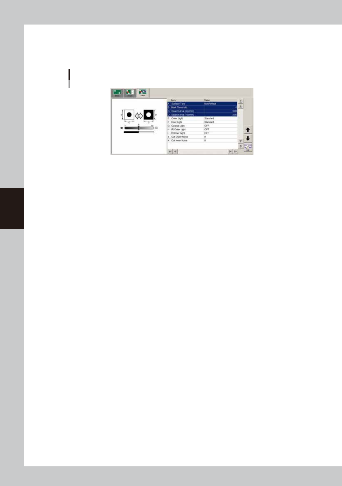
Set the vision parameters.
Open the [Mark]-[Vision] tab and set the vision parameters as needed. Bonding adhesive and solder do
not reflect light, so set the “Surface Type” parameter to “NonReflect”. Set the other parameters in the
Mark Adjust mode. For details on each parameter, see “
n
Mark recognition information”.
Mark shape information
64434-N7-00
4-17
4
Making the dispensing stable
n
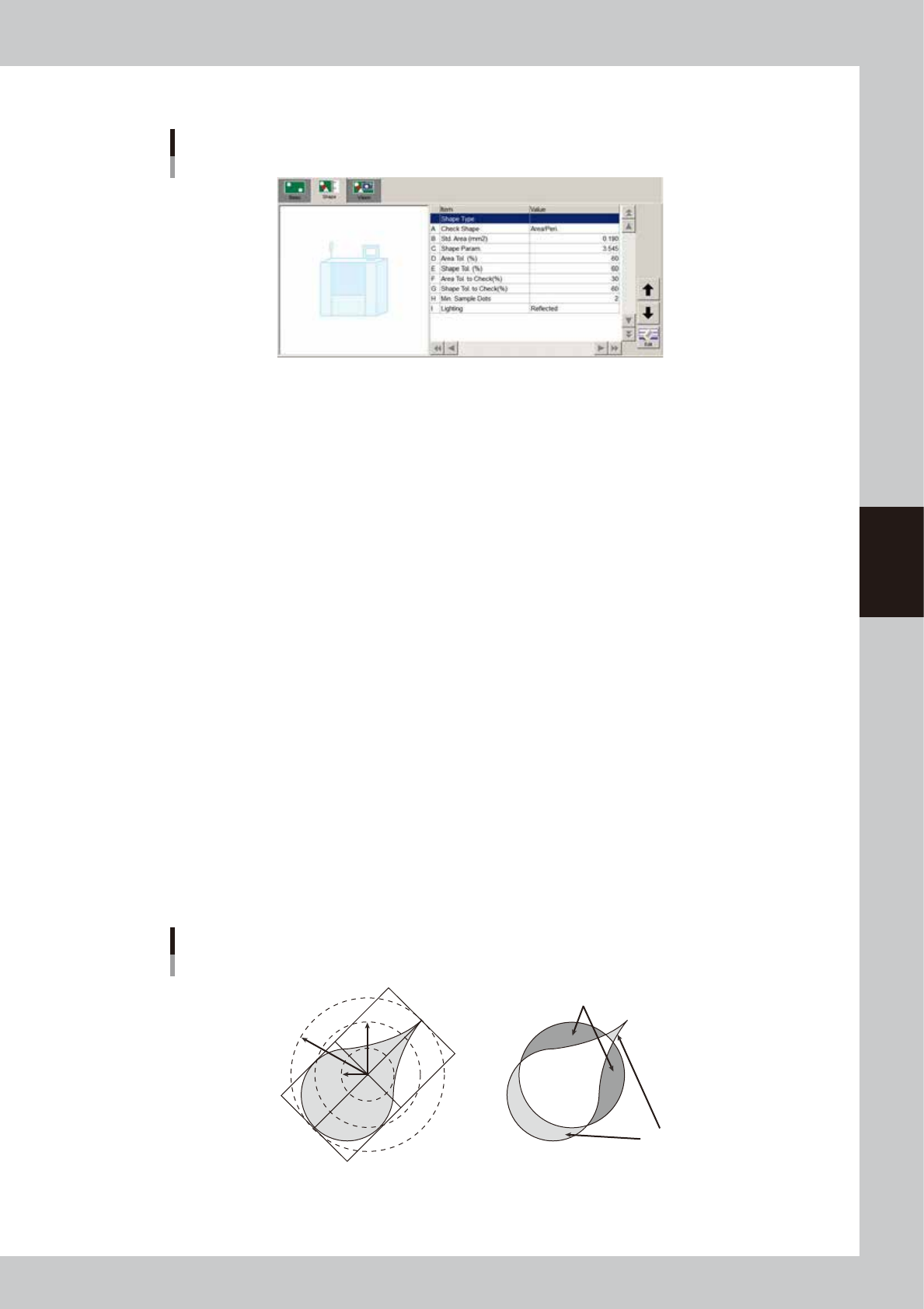
Mark shape information
Mark shape information
64435-N7-00
A: Check Shape
Normally, set this parameter to “RoundLevel”.
• Area/Peri.
This uses a formula of (dot perimeter /
√
dot area) to calculate the shape and checks whether this calculated value is
within the shape tolerance range that is specified on the basis of the shape constant set in the mark information.
The calculated value of (dot perimeter /
√
dot area) should uniformly approach 3.545 in the case of circle, and should
approach 4.000 in the case of square, so this value allows determining whether the dot is near the target shape or not.
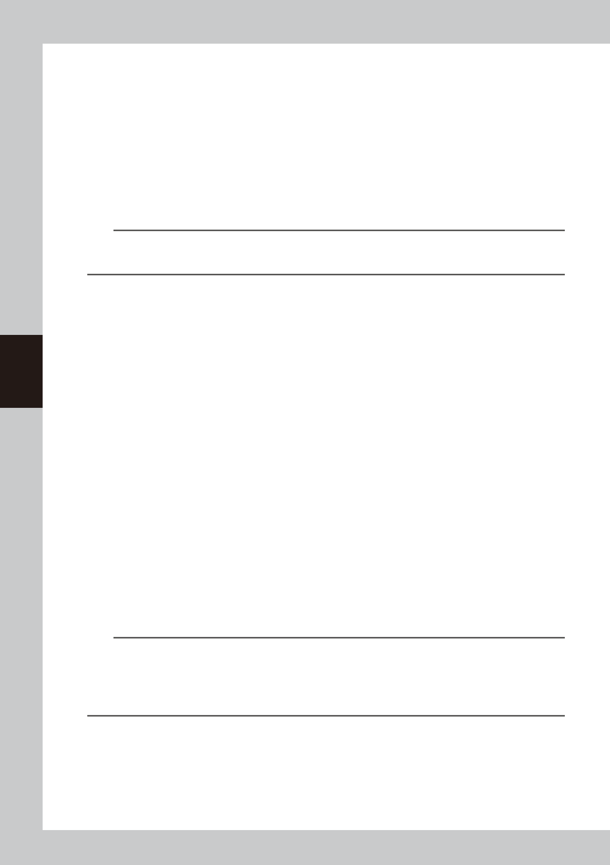
• RoundLevel
This checks the shape based on the inscribed and circumscribed circles surrounding the dot in order to check whether
a cobwebbing occurs.
The intermediate radius R { (Rmin + Rmax) / 2 } is found from the radius of the inscribed circle (Rmin) and the radius
of the circumscribed circle (Rmax) for the recognized dot, and then checks are made as to whether the radius of the
inscribed circle and the radius of the circumscribed circle are within the shape tolerance range that is specified on the
basis of the intermediate radius.
When the minimum radius is smaller than the intermediate radius (R) x (1 – shape tolerance / 100), it is out of the
tolerance.
When the maximum radius is larger than the intermediate radius (R) x (1 + shape tolerance / 100), it is out of the
tolerance.
If the dot approaches a perfect circle, then the maximum radius and minimum radius are near the intermediate radius.
• Matching
This finds the area of irregularities (concavities/protrusions) overlapped on a perfect circle (circle with an area
equivalent to the dot)
Area of protrusion (Area1) = Area of section (blue color) sticking out from perfect circle
Area of concavity (Area2) = Area of section (red color) not outside of dot within perfect circle
Area of dot (AreaDot) = Area of perfect circle
The area ratio of irregularities (concavities/protrusions) is then obtained by (Area1 + Area2) / AreaDot and is checked
as to whether it is within the shape tolerance.
When approaching a perfect circle, the area ratio of irregularities is a value of nearly 0 (=0%).
When deviating from a perfect circle, it is a value near 1 (=100%).
Shape check method
RoundLevel Matching
Area1
Area2
Rmax
Rmin
R
63409-N7-00
4-18
4
Making the dispensing stable
B: Std. Area
Enter the main liquid amount to dispense a dot. If there is a difference between the dots on a board and on the dot
station, set this parameter to the liquid amount for the dot on the board.
C: Shape Param.
When the “Check Shape” parameter is set to “Area/Peri”, set the shape constant.
Set this shape constant to “3.545” when the shape to be extracted is a circle, and set it to “4.000” when the shape is a
square.
Shape constant = Perimeter /
√
Area
D: Area Tol.
This is a tolerance used to evaluate dot recognition results. As this parameter value approaches 100%, the evaluation
criteria become less strict.
n
NOTE
To make it easier to obtain the area data, set the area and shape tolerance values to 100%.
This helps you acquire the data easily. After you have acquired the area data, return the parameters to the original
settings.
E: Shape Tol.
This is a tolerance used to evaluate dot recognition results. As this parameter value approaches 100%, the evaluation
criteria become less strict, so even dots forming a long adhesive string are viewed as okay.
F: Area Tol. to Check (for check)
This is a tolerance used to evaluate the second dot recognition results when the alignment amount check function is
used. As this parameter value approaches 100%, the evaluation criteria become less strict.
G: Shape Tol. (for check)
This is a tolerance used to evaluate the second dot recognition results when the alignment amount check function is
used. As this parameter value approaches 100%, the evaluation criteria become less strict, so even dots forming a long
adhesive string are viewed as okay.
H: Min. Sample Dots
Set the number of dots that can be recognized correctly to continue production.
If "0" is set, production will continue irrespective of the recognition result.
It is recommended that predispensing for alignment be performed twice by each head prior to recognition.
An error will occur if the number of dots that can be recognized does not reach the value set for the "Min. Sample Dots"
parameter. (Refer to "8.2.6 Checking alignment during automatic operation".)
When you press the [ERROR CLEAR] button, the [Dispense Test], [Retry]. [Reset] and [Continue] buttons are displayed.
(See “2.3 Starting a dispensing test during automatic operation” in this chapter.
• Continue
Continues automatic operation.
If you click this button after recognition of all the dots has failed, dispense will be performed on the board based on
the previous alignment amount.
• Retry
If you click this button after recognition of all the dots has failed, dispense will be performed again.
• Reset
Stops automatic operation and releases the board.
TIP
When you perform recognition twice, two dots will be recognized with a 1-shot nozzle and four dots with a 2-shot
nozzle.
When the "Min. Sample Dots" parameter is set to "3" when a 2-shot nozzle is used, production will stop if the number of
correctly recognized dots is 2 or less.
If you want to let production stop when predispensing becomes unstable, set the "Min. Sample Dots" parameter to the
maximum number of dots which can be considered to be a sample.
I: Lighting
Set to "Reflected" when recognizing dispensed dots with the moving camera installed on the head assembly.
Set to "Backlight" when using the lighting on the dot station (option).