YSD_Users_E.pdf - 第124页
3-11 3 Q & A 4. Low-liquid sensor functions This section describes the functions that are effective when the normal low-liquid sensing cannot detect whether the liquid has run out. 4.1 Remaining amount detection angl…
3-10
3
Q & A
3. Reducing paper consumption
This section describes the function for reducing consumption of paper in the dot station.
3.1 Predispensing interval setting
This function specifies the intervals in the predispensing operation by number of boards or by time. Specifying
the predispensing interval reduces the dispensing count (number of dispensing operations) onto the paper in
the dot station and allows reducing the paper consumption quantity. (This is settable for each head.)
n
Setting range
• Board count interval : 0 to 999 boards
• Time interval (sec) : 0 to 30000 seconds
Either the time interval or board interval can set to run predisposing.
n
Example of operation by board interval
The table below shows an example where the setting for Head 1 is “2” and the setting for Head 2 is “4” as the number of
boards.
Head No. / Number of boards First board Second board Third board Fourth board Fifth board
Head 1 Run - Run - Run
Head 2 Run - - - Run
Set the interval.
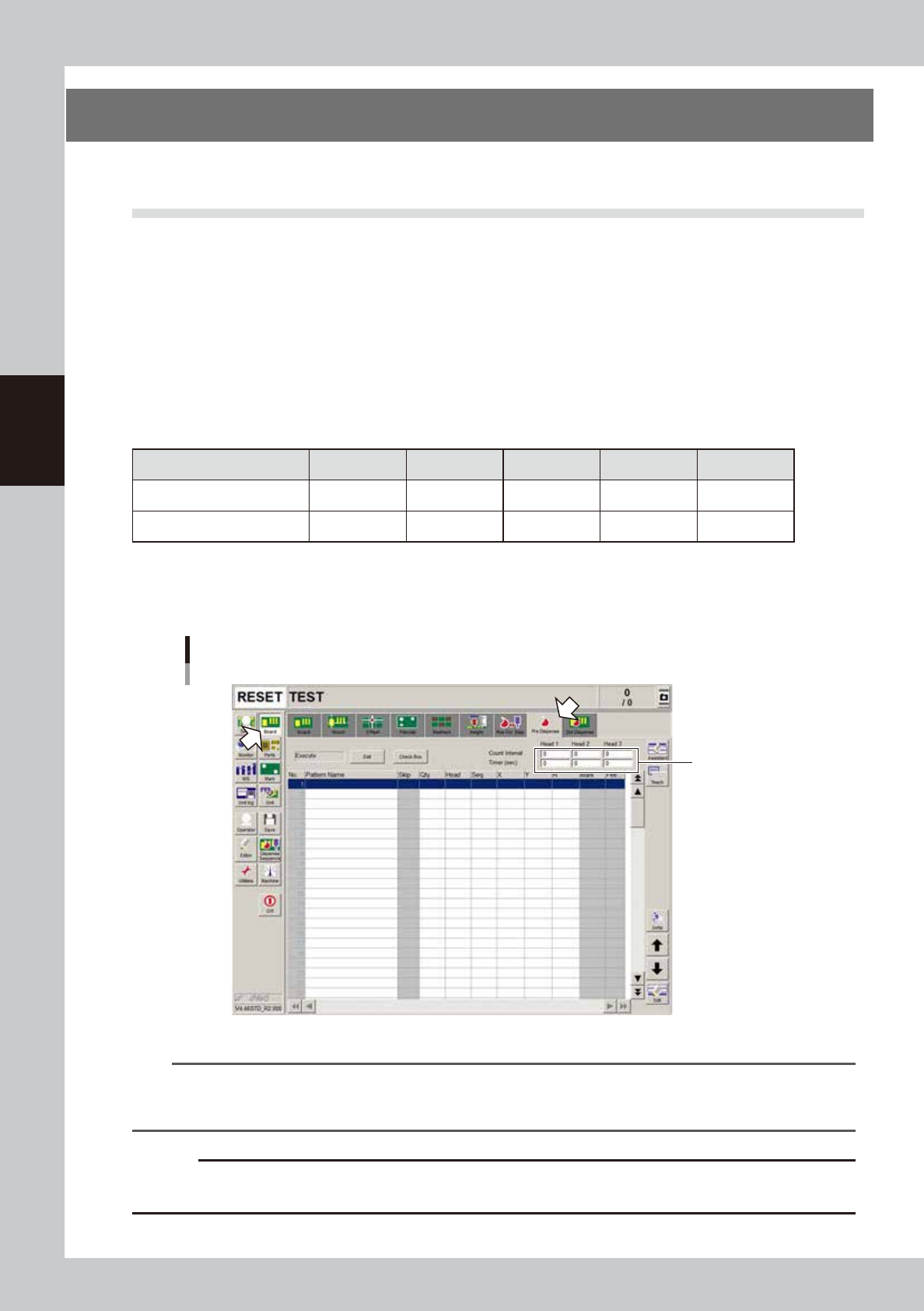
1. Open the [Board] – [Pre-dispense] screen
2. Enter the board count interval and time interval (sec.).
Predispensing interval setting
Enter the interval settings.
64300-N7-00
n
NOTE
In continuous production, first set an interval of every 2 boards as shown below.
• Board count interval : 2 boards
• Time interval : Cycle time + about 10 seconds
c
CAUTION
If the interval is set too large, then the initial number of dots from will be extremely little. Increase the interval gradually
so that no problem occurs with the dispensing operation.
3-11
3
Q & A
4. Low-liquid sensor functions
This section describes the functions that are effective when the normal low-liquid sensing cannot detect
whether the liquid has run out.
4.1 Remaining amount detection angle setting
When the normal low-liquid sensing cannot detect the liquid and so fails to determine whether the liquid has
run out, use the function that detects the reflected light from the piston. To enable this function, set the amp
output selector switch is set to “D_ON” and set the detection angle.
TIP
This function can be used with either “D_ON” or “L_ON” setting. But in most cases, set the amp output selector switch
to “D_ON” when detecting the piston.
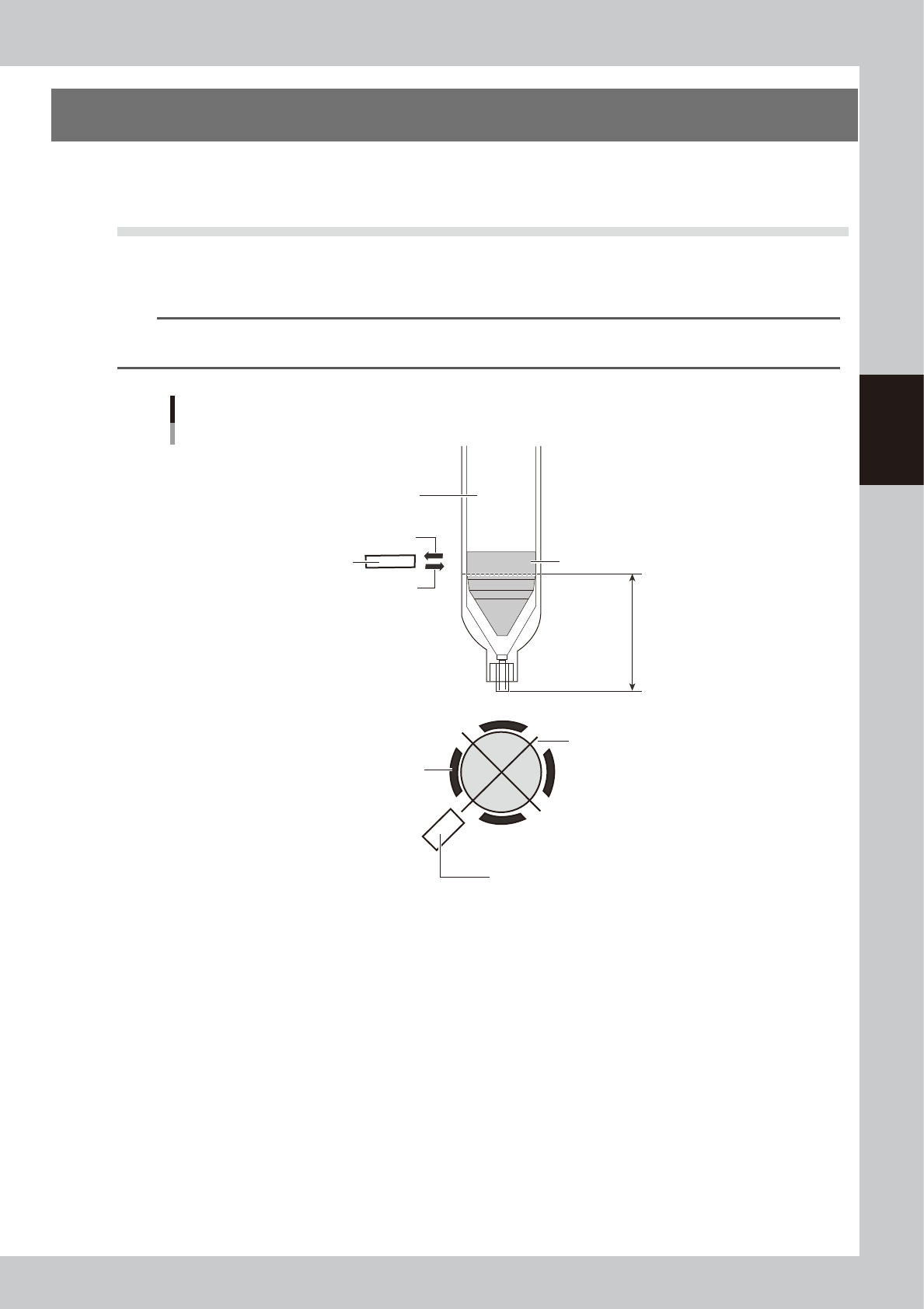
Overview of angle setting
Piston detection position
Low-liquid sensor
Syringe holder
Piston bottom end
(no liquid remains)
Hole in the syringe holder
opens each 90 degrees
Low-liquid sensor
Syringe (clear)
Sensor optical axis (reflected light)
Sensor optical axis (emitted light)
63301-N7-00
n
Operation overview
After producing one board, this function makes a remaining liquid check at the 4 angles of +90°+180°+270°and the
specified angle. (Four angles are used because correct detection is sometimes impossible with only one point due to the
portions where the liquid was not scraped evenly.)
If a liquid outage is detected, then an error appears after one board is produced.
(Error display timing might be somewhat delayed compared to normal remaining liquid detection)
n
Item restrictions
• The remaining liquid might not be detected due to the syringe being used.
• All heads must detect the remaining liquid at the same R-axis angle.
• Cycle time might be slow depending on the board data.
On the [Board] - [Board] screen, “Precede Check” should be set to “Use”.
* Cycle time might sometimes be slow or delayed when the distance from the final dispensing coordinates to standby
position is short.
3-12
3
Q & A
4.1.1 Adjusting the low-liquid sensor (angle setting)
e
1
Press the emergency stop button.
The machine must be in emergency stop to ensure safety during work.
2
Check the amp signal output setting.
Set the amp output selector switch to the “L_ON” side so that the low-liquid sensor stays on when it is
detecting the dispensing liquid in the syringe.
TIP
This function can be used with either “D_ON” or “L_ON” setting. But in most cases, set the amp output selector switch
to “D_ON” when detecting the piston.
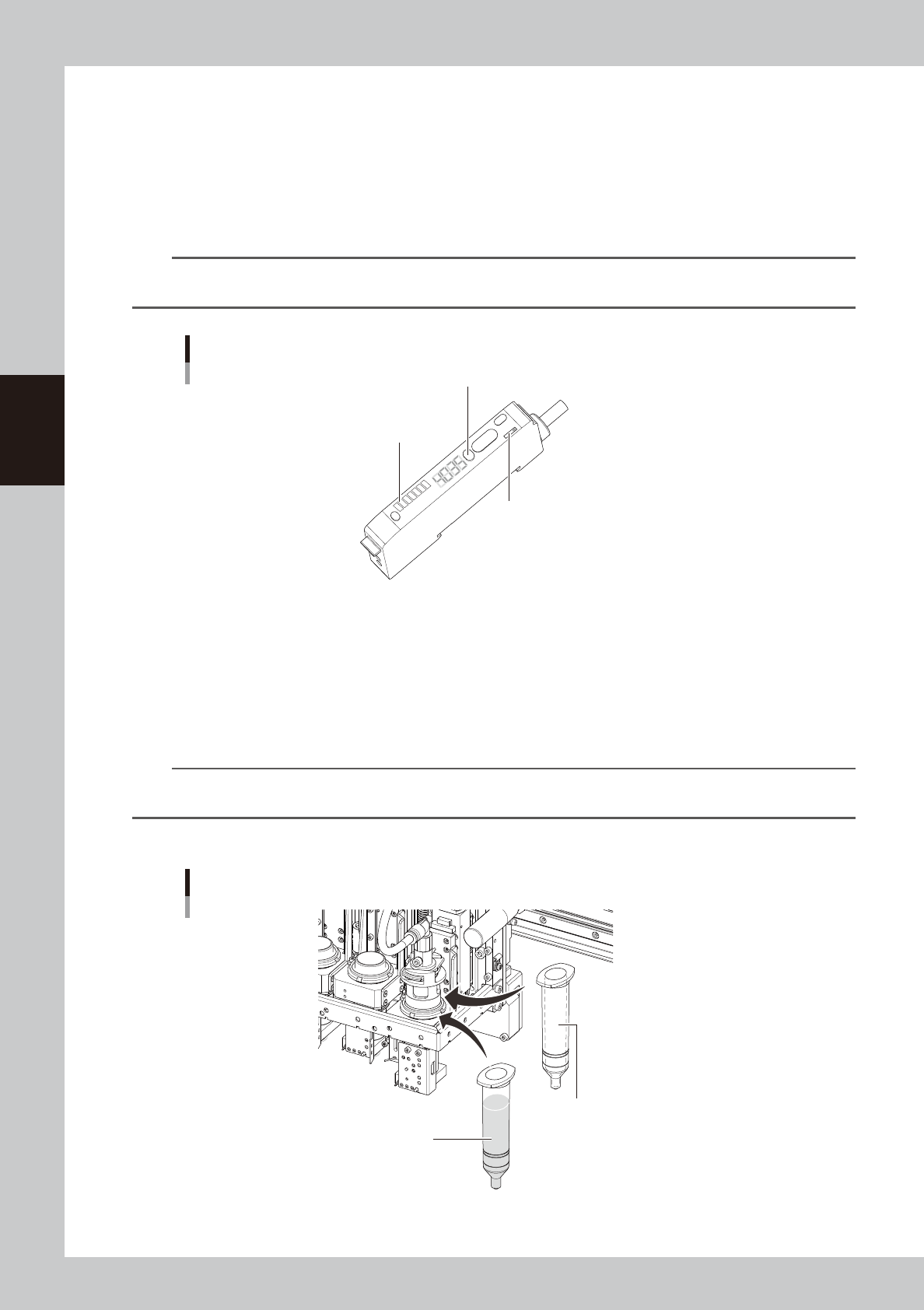
Low-liquid sensor amp section
Auto SET button
Calibration indicator (orange)
Output selector switch
63302-N7-00
3
Adjust the low-liquid sensor level.
1. Set the empty syringe into the head section.
2. Check that the sensor optical axis is along the piston detection position in the used syringe.
3. Allow the sensor beam to strike the syringe.
The holder in which the syringe is set contains 4 openings. Rotate the R-axis so that the sensor faces
the opening where the highest value is obtained.
n
NOTE
If the sensor height needs to be adjusted, loosen the two bolts holding the sensor bracket and slide the sensor up or
down.
4. Press the Auto SET button on the amp and check that the calibration indicator is lit up.
Setting the syringe
Step 3
Empty syringe
Step 4
Syringe full of liquid
63303-N7-00