YSD_Users_E.pdf - 第182页
4-54 4 Making the dispensing stable 8. Down Speed (%) Set the speed at whic h the Z axis moves do wn to dispense adhesiv e. T he speed must be set in percentage to the maximum rpm of the Z-axis motor . Normally , set 100…
4-53
4
Making the dispensing stable
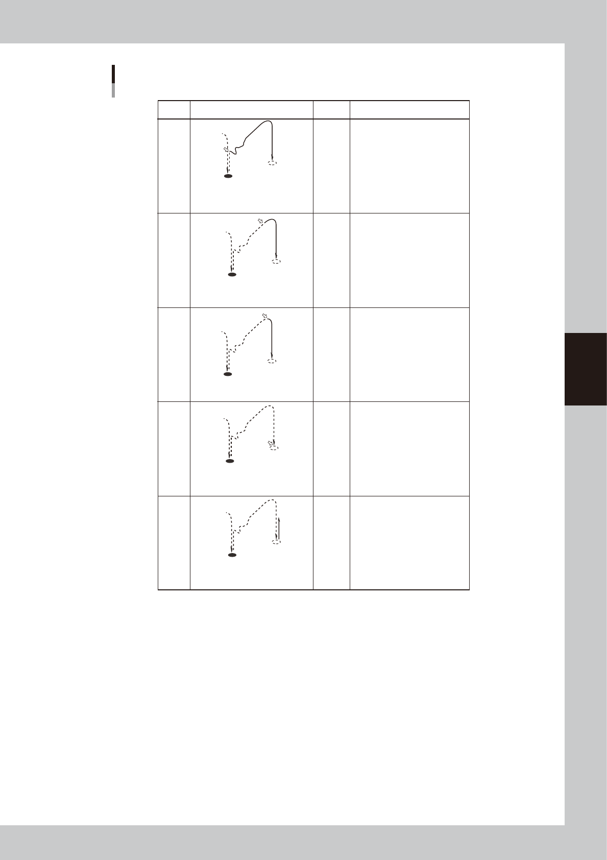
Dispense start trigger
ON
ON
ON
ON
ON
Setting Movement Dot size Description
Less than
1.5mm
More than
3.0mm
More than
3.0mm
1.5 to
3.0mm
Use this setting in most cases
when using a 2-shot nozzle for
small amounts.
–
The dispensing air valve turns on at
the same time the XY axes move
towards the next dispensing point.
If the dispensing position is not
stable with "XY-POS" due to
adhesive fluctuation at the nozzle
tip, select this setting.
Also set the "Timer before up"
parameter.
If the dispensing position is not
stable with "XY-DOWN" due to
adhesive fluctuation at the nozzle
tip, select this setting.
Also set the "Timer before up"
parameter.
This setting is not used in most
cases.
If you want to set the Z-axis
movement at extremely slow
speeds and produce tall dispensing
dots, select this setting.
The dispensing air valve turns on
when the XY axes reach the tolerance
range of the next dispensing point.
The dispensing air valve turns on at
the same time the Z-axis begins to
move down to the dispensing point.
The dispensing air valve turns on at
the same time the Z-axis begins to
move up from the dispensing point.
The dispensing air valve turns on at
the same time the Z-axis reaches the
dispensing point.
Z-UP
Z-DOWN
XY-POS
XY-GO
Z-LOW
If the dispensing position is not
stable with "XY-GO", probably
because of adhesive fluctuation at
the nozzle tip, select this setting.
Use this setting in most cases
when using a 1-shot nozzle.
63420-N7-00
5. Timer after disp (msec)
Set the time to be elapsed after the valve has performed dispensing. This parameter is useful when the diameter of
dispensed dots varies with the travel distance of the XY axes.
If the diameter varies when adhesive is dispensed at short intervals even though the same amount of adhesive is
dispensed, set this parameter to between 20 and 50ms.
6. Head down with outpos
This allows the Z axis to move down after the movement on the X and Y axes is complete.
7. Lower Position (mm)
Specify the dispensing height from the board surface. Add a "+" sign if the position is above the board surface, and add a
"-" sign if it is below the board surface.
If the nozzle stopper does not provide good contact due to upward or downward warp of the board even though a correct
height has been specified for this parameter, set it as follows.
• Enter a minus value if no contact is made by the nozzle stopper.
• Enter a plus value if the nozzle stopper makes excessive contact on the entire board.

4-54
4
Making the dispensing stable
8. Down Speed (%)
Set the speed at which the Z axis moves down to dispense adhesive. The speed must be set in percentage to the maximum
rpm of the Z-axis motor. Normally, set 100%.
However, if the adhesive on the nozzle tip is not dispensed on the board but adheres to the external surface of the
nozzle, decrease this speed.
9. Time before up (msec)
Set the time to be elapsed before the Z axis starts to ascend after reaching the target descent position. Set this parameter
if no adhesive is dispensed on the board or if it scatters.
To prevent cobwebbing when using adhesive (e.g. cream solder) that requires sometime before it familiarizes with the
board, set this parameter to between 50 and 200 ms.
10. Slow Down Distance (mm)
Set the height where the Z axis starts to slow down during descent.
11. Slow Down Speed (%)
Set the speed at which the Z axis starts to move down. The speed must be set in percentage to the maximum rpm of the
Z-axis motor. However, if the adhesive on the nozzle tip is not dispensed on the board but adheres to the external surface
of the nozzle, decrease this speed.
12. Upend Position (mm)
Set the target position to which the Z axis moves up after dispensing. A height from the board surface must be entered. A
value that is equal to or larger than "Z height for next job" must be entered.
Set a larger value if the summit of dots is drawn in the direction the head moves.
If the height can be decreased, make it as small as possible to improve tact.
13. Up Speed (%)
Set the speed at which the Z axis starts to move up after dispensing. The speed must be set in percentage to the maximum
rpm of the Z-axis motor. Decrease the speed if adhesive drips or scatters due to cobwebbing.
If cobwebbing occurs even if the nozzle has proper contact with the board, decrease this speed by 10%.
14. Timer Bedor XY move (msec)
Set the time to be elapsed before the XY axes start to move at the top-end position after the Z axis completes dispensing.
If you are using adhesive that often causes cobwebbing but does not require the Up Speed to be reduced, set this
parameter to between 30 and 100.
15. Slow Up Distance (mm)
Set the height where the Z axis starts to slow down before moving to the target position after dispensing. A height from
the board surface must be entered.
16. Slow Up Speed (%)
Set the speed at which the Z axis starts to slow down before reaching the target position after dispensing. The speed must
be set in percentage to the maximum rpm of the Z-axis motor. Decrease the speed if adhesive drips or scatters due to
cobwebbing.
17. Z height for next job (mm)
Set the height where the XY axes can be operated when the Z axis moves up after dispensing. A value from the board
surface must be set, and if obstructions (e.g. components) that project beyond the board surface are present, a value that
is larger than the highest obstruction by one mm or more must be entered. If adhesive drips or scatters due to
cobwebbing, such problems may be reduced by increasing this parameter together with "Up Speed". If this height is not
appropriate, there is a possibility that the nozzle collides with the obstructions on the board.
Set a larger value if the summit of dots is drawn in the direction the head moves.
If the height can be decreased, make it as small as possible (minimum: 35) to improve tact.
18. Comment
Enter a comment regarding the dispense sequence.
19. Dispense Pulse Width (msec)
Normally, set "0".
20. Dispense Pulse Interval (msec)
Normally, set "0".
4-55
4
Making the dispensing stable
7. Checking/correcting dispensing positions
This section explains how to check and correct the dispensing position specified in the dot dispense
information, using the trace function and teaching function or direct data input. The trace function moves the
teaching unit to the coordinates displayed on the screen. If you select “Camera” for the teaching unit, you
can visually check the position on the vision monitor.
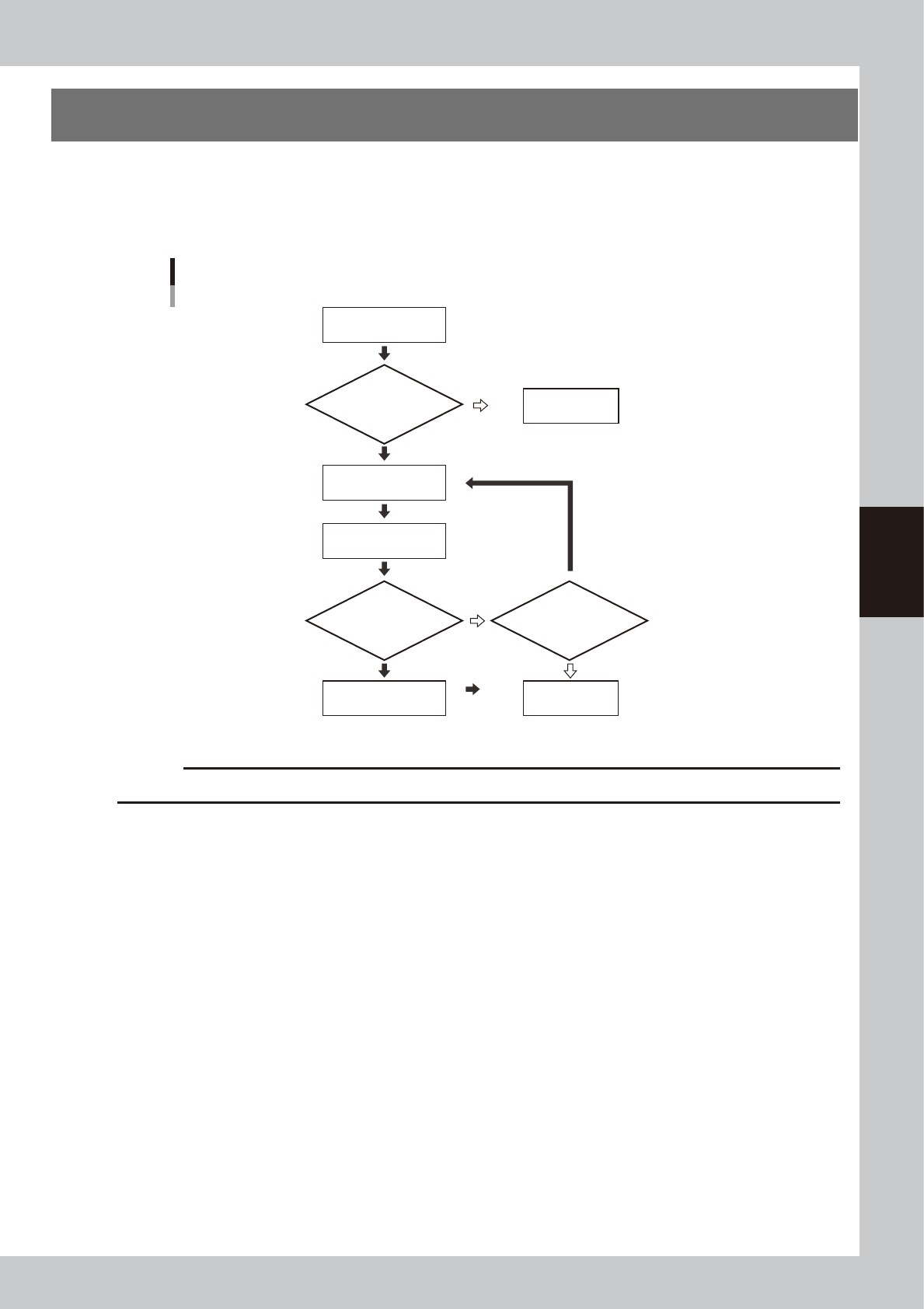
Flow chart for checking and correcting the dispensing position
Select dispense
No. to check position
Open dot dispense
information
Check dispensing
position
Enter correct coordinate
data by teaching
Save data
Is board clamped?
Correct dispensing
position?
Continue work?
Secure board.
YES
YES NO
NO
NO
YES
63421-N7-00
c
CAUTION
Dot dispense information will be overwritten if you perform dispensing distribution again.