YSD_Users_E.pdf - 第236页
5-47 5 Creating the board data 5.4 Ball lead components T his section describes how to set data for ball lead parts such as BGA and flip chip. 5.4.1 BGA components When "Alignment T ype" of the Basic parameters…
5-46
5
Creating the board data
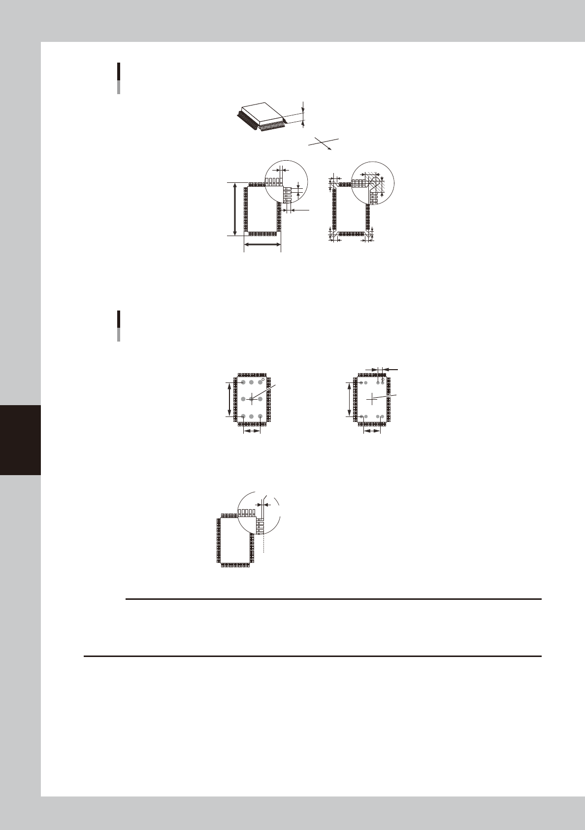
Shape parameters for QFP
Bottom view
A : Body Size X
B : Body Size Y
C : Body Size Z
H : Lead Pitch
I : Lead Width
J : Reflect LL
K : Bumper Mask
C
S
E
W
N
B
A
I
H
K
K
K
K
K
K
K
K
J
63530-N7-00
Dispense parameters
■ 1-shot nozzle (solder)
Reference position X
■ 2-shot nozzle (bond)
Varies with 2-shot
nozzle pitch.
Center of component
■ 1-shot nozzle (bond)
(3 points in both X and Y directions)
Y-directional
dot extent
X-directional dot extent
Center of component
Y-directional
dot extent
X-directional dot extent
Lead end position
Reference position (0.00)
Dispense for QFP components
65331-N7-00
c
CAUTION
• When using solder paste for QFP components, the amount of solder paste may be insufficient if dispense is
performed only once for each lead.
• When using solder paste for QFP components, dispense may not be possible if the lead pitch is 0.8 mm or
narrower.
5-47
5
Creating the board data
5.4 Ball lead components
This section describes how to set data for ball lead parts such as BGA and flip chip.
5.4.1 BGA components
When "Alignment Type" of the Basic parameters is set to “Simple BGA” or "BGA", BGA components are
registered with the parameters shown below.
For parameters not explained here, refer to the description in "5.2 Chip Components" of this chapter.
c
CAUTION
The solder distribution is not supported for ball components. When using solder, teach the data obtained by dispense
distribution or edit the dot dispense information.
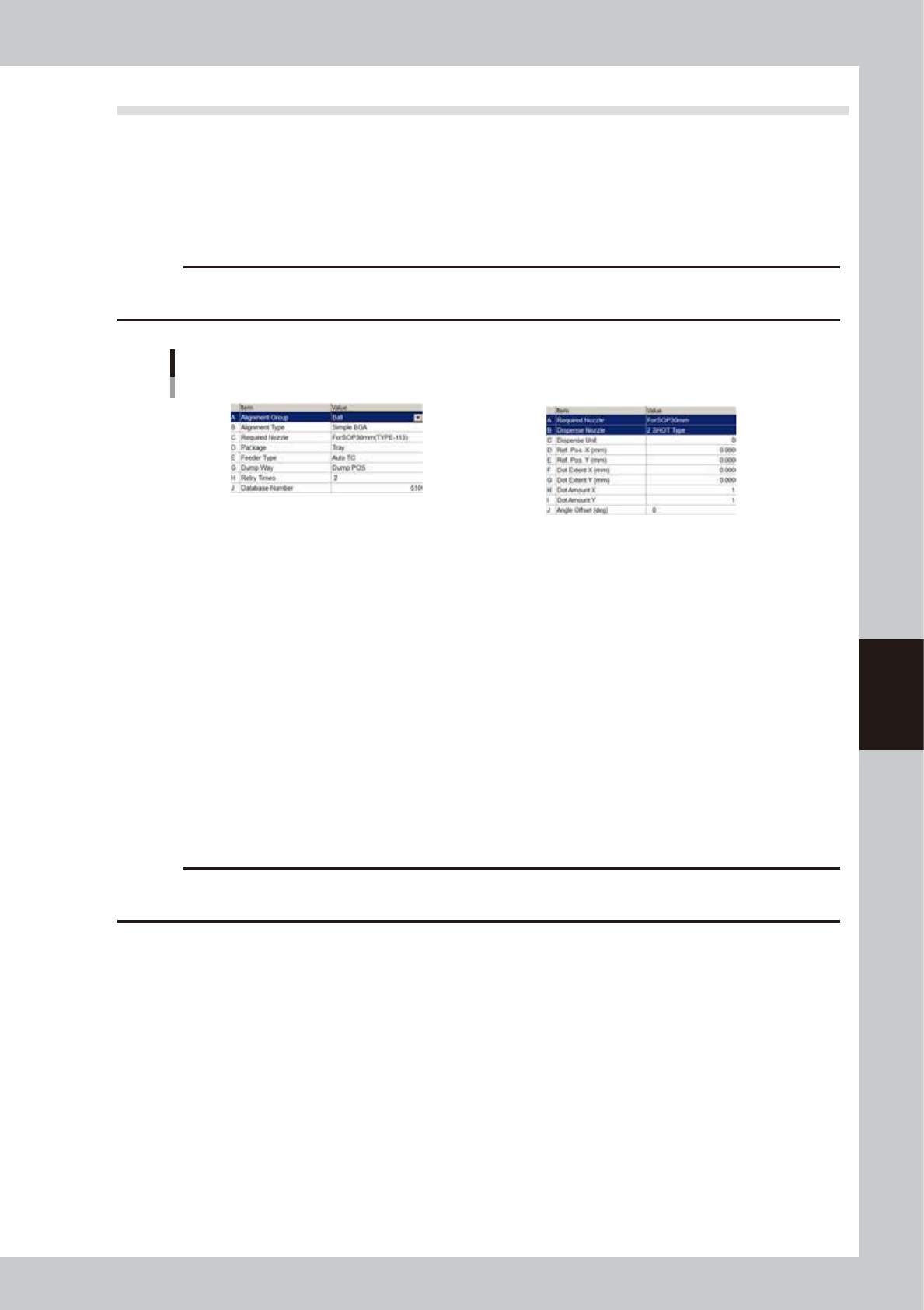
BGA component parameters
Basic
Dispense
64527-N7-00
Basic parameters
A: Alignment Group
Set this parameter to “Ball”.
B: Alignment Type
Set to "Simple BGA" or "BGA".
Enter the distance between each terminal.
Dispense parameters
Bond type adhesive is not used for ball lead components.
To use solder paste, perform teaching for the data after it has been subjected to dispense distribution or edit the dot
dispense information.
For instance, assuming that Dot Extent X =24, Dot Extent Y = 24, Dot Amount X = 3 and Dot Amount Y = 3, coordinate
data for 3 points for both X and Y directions will be created by performing dispense distribution.
So, delete unnecessary coordinate data from the dot dispense information screen.
c
CAUTION
When using solder paste for ball lead components, dispense may not be possible if the ball pitch is 0.8 mm or
narrower.
5-48
5
Creating the board data
5.5 Connector components
Connector components are registered with the parameters shown below. For parameters
not explained here, refer to the description in "5.2 Chip Components" of this chapter.
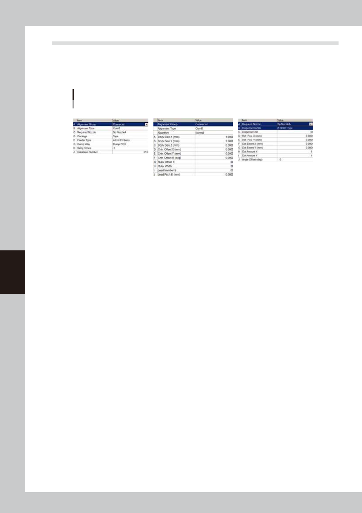
5.5.1 Connectors
Connector component parameters
Basic Shape Dispense
64528-N7-00
Basic parameters
A: Alignment Group
Set this parameter to “Connector”.
B: Alignment Type
Set to “Con-E”.