YSD_Users_E.pdf - 第81页
2-21 2 Basic operation 3.3.3 Adjusting the board hold plates T he board hold plates hold the edges of a board from above when the board is clamped. Adjust the positions of the board hold plates as needed. Each plate is i…
2-20
2
Basic operation
3.3.2 Changing the conveyor width
First adjust the conveyor width to match the board width to be produced.
1
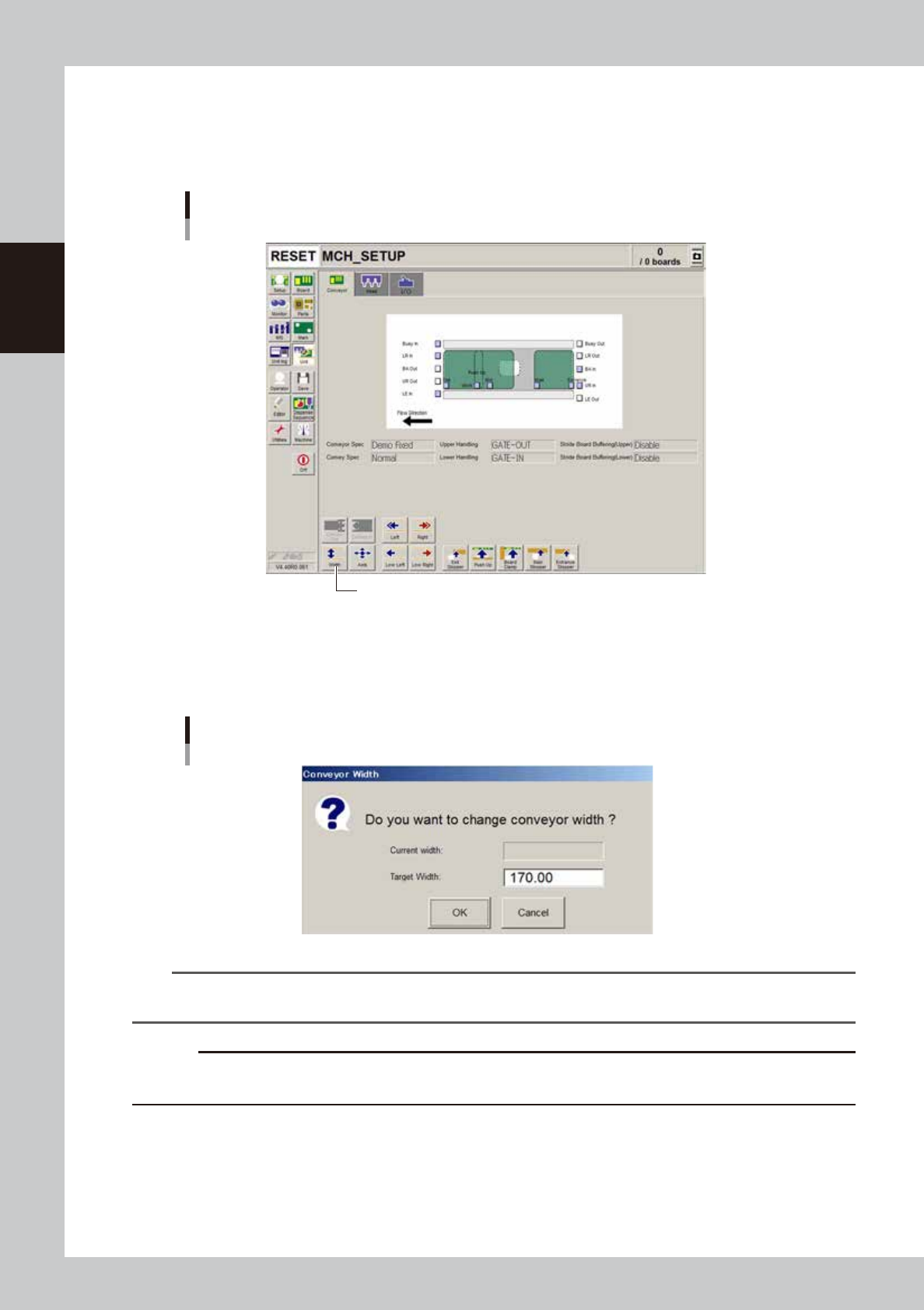
Open the [Unit]-[Conveyor] tab screen.
[Unit] - [Conveyor] screen
[Width] button.
64210-N7-A0
3
Press the [Width] button.
The Conveyor Width dialog box appears. Check the conveyor width and press the [OK] button. The
conveyor rail automatically changes to the specified width.
Conveyor Width dialog box
64211-N7-00
TIP
When board data has been loaded, the conveyor width of the board data is displayed in the “Target Width” box in
the dialog box.
c
CAUTION
When push-up pins are set on the push-up plate, make sure that they do not touch the conveyor rail while adjusting
the conveyor width.
2-21
2
Basic operation
3.3.3 Adjusting the board hold plates
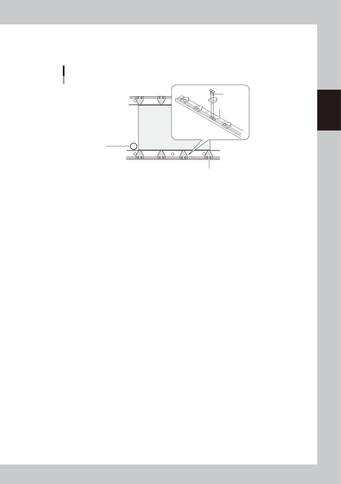
The board hold plates hold the edges of a board from above when the board is clamped. Adjust the positions of
the board hold plates as needed. Each plate is installed with M3 screws on the conveyor rails.
PCB
Board hold plates
M3 screw
Movable conveyor rail side
Fixed conveyor rail side
Board hold plate
M3 nut
Main stopper
63207-N7-00
1
Raise the main stopper.
On the [Unit]–[Conveyor] tab screen, press the [Main Stopper] button to raise the main stopper.
e
2
Place the machine in emergency stop.
Press the emergency stop button on the operation panel to turn off the servo.
3
Set a board on the conveyor.
Open the safety cover and set a board on the conveyor by placing it against the main stopper.
4
Adjust the positions of the board hold plates.
Loosen the screws with a screwdriver and adjust the positions of the board hold plates to match the
board size.
5
Cancel emergency stop.
Close the safety cover, release the emergency stop button, and press the [READY] button.
2-22
2
Basic operation
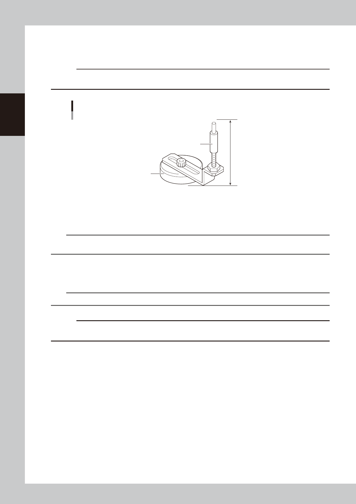
3.3.4 Arranging the push-up pins
The push-up pins are attached on the push-up plate by a magnet and used to correct downward warping of the
board.
c
CAUTION
The push-up pin height from the bottom of the magnet to the top of the pin shaft is set to 76 mm. Do not change this
height.
76mm
Support pin
Pushup pin
Magnet stand
63208-N7-00
1
Raise the push-up plate.
Check safety and press the [Push Up] button on the [Unit]–[Conveyor] tab screen. A dialog box for
board thickness input then appears. Enter the thickness of the board in millimeters and press the [OK]
button. The push-up plate will move up.
TIP
When board data has been loaded, the board thickness of the board data is displayed in the “Thickness” box in the
dialog box.
2
Place the push-up pins in the correct positions on the push-up plate.
Considering the shape and size of the board, place the push-up pins on the push-up plate so that they
uniformly support the board, including the edge of the board.
n
NOTE
Place as many push-up pins as possible on the push-up plate to support the board evenly.
c
CAUTION
Set the push-up pins in positions where they will not interfere with the conveyor rails and other parts when the push-up
plate is raised.
3
Cancel emergency stop.
Close the safety cover, release the emergency stop button, and press the [READY] button.
e
4
Set a board on the conveyor.
1. Press the [Push Up] button on the [Unit]–[Conveyor] tab screen to lower the push-up plate.
2. When the main stopper has been lowered, press the [Main Stopper] button on the [Unit]–[Conveyor]
tab screen to raise the main stopper.
3. Open the safety cover and set a board on the conveyor by placing it against the main stopper.
5
Cancel emergency stop.
Close the safety cover, release the emergency stop button, and press the [READY] button.