YSD_Users_E.pdf - 第137页
4-9 4 Making the dispensing stable Flowchart when using dispense correction Create mark data for dot recognition (For dot area measurement) Create predispensing parameters (Copy and edit parameters or enter from keyboard…
4-8
4
Making the dispensing stable
3. Creating the predispensing information
Normally, dispense correction is perform by predispensing to ensure that dispensing liquid is smooth and
stable before starting dot dispensing. This information is called predispense information. The procedure for
creating the predispense information is described below.
3.1 Using the dispense correction function
The dispense correction function corrects changes over time in the dispensing dot size formed by the dispenser
machine, by increasing or decreasing the dot dispensing air output time based on the average area of the
sample dots obtained by the predispensing test. This function works properly in combination with the optional
dot station. If the predispensing is performed on a board, this function can be used only when dot recognition
on the board is sufficiently stable. This section describes an example of use with the dot station.
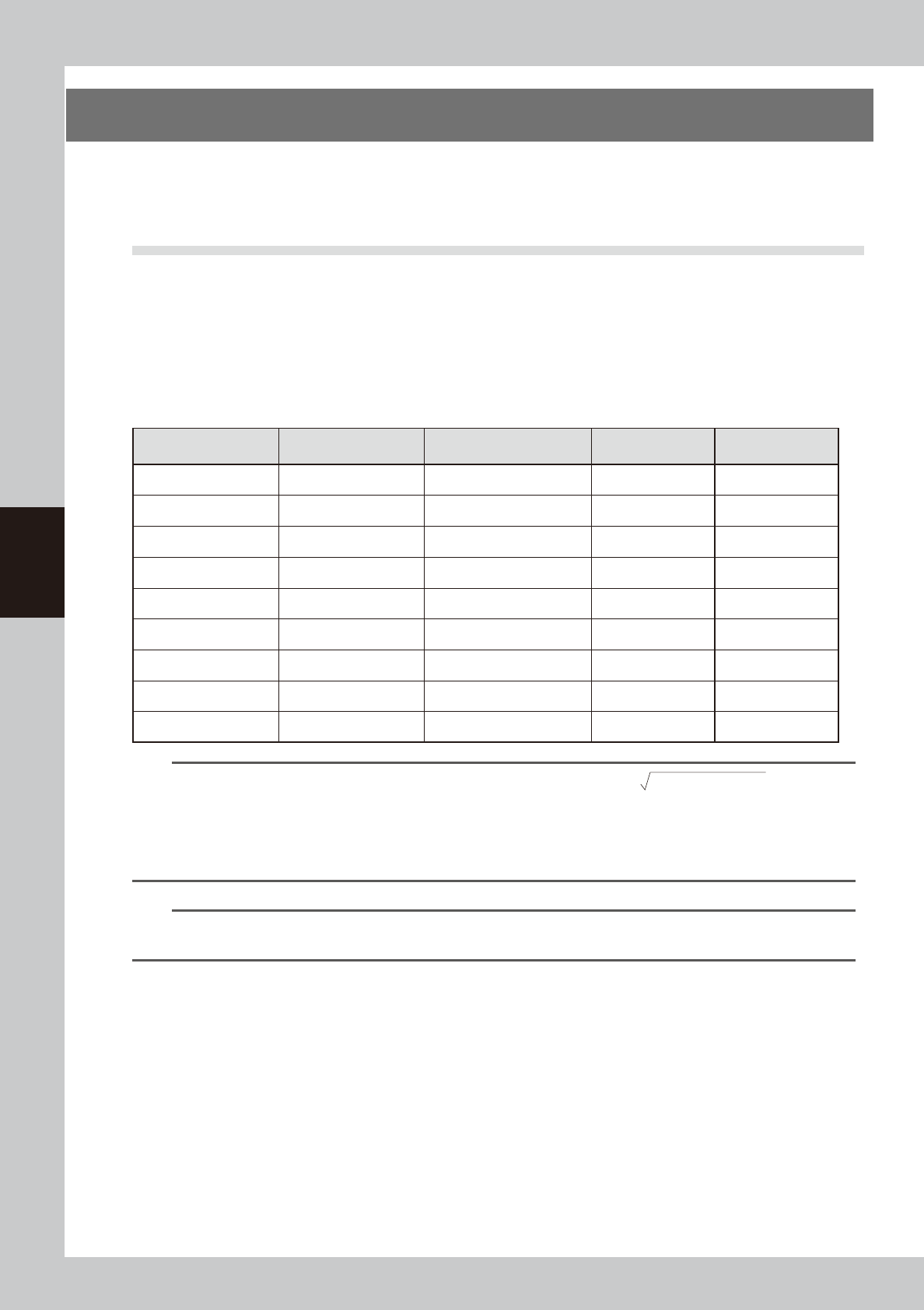
For the settings for each nozzle, refer to the table below.
n
Nozzle settings (YAMAHA default values)
Nozzle/ No. of
dispensings
Nozzle inner diameter
[mm]
Standard area [mm
2
]
(when liquid amount is 20)
Mark No. Correction type
111 (2-point) 0.4 0.19 11 Type 11
112 (2-point) 0.5 0.29 12 Type 12
113 (2-point) 0.9 0.95 13 Type 13
114 (1-point) 0.4 0.19 14 Type 14
115 (1-point) 0.8 0.75 15 Type 15
116 (1-point) 1.5 2.65 16 Type 16
11A (2-point) 0.4 0.19 20 Type 20
11B (1-point) 1.0 1.18 21 Type 21
11C (1-point) 1.3 1.99 22 Type 22
TIP
• The dot diameter can be found from the dot area size, using the calculation of
(dot area /3.14x2)
.
• Refer to the following values to find the liquid amount for each part
1608 chip Dot diameter of about 0.6 mm (Area 0.28 mm
2
)
2012 or larger chips Dot diameter of about 0.8 mm (Area 0.50 mm
2
)
SOP Dot diameter of about 1.0 mm (Area 0.79 mm
2
)
n
NOTE
The standard area is set using the liquid amount for the main dispensing as a general guide, so change if needed.
(YAMAHA default value for liquid amount is 20.)
4-9
4
Making the dispensing stable
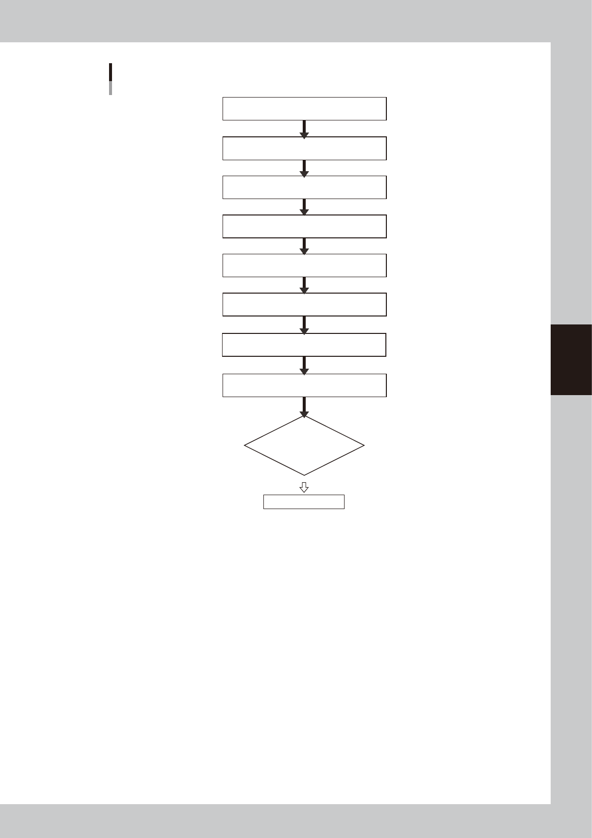
Flowchart when using dispense correction
Create mark data for dot recognition
(For dot area measurement)
Create predispensing parameters
(Copy and edit parameters or enter from keyboard)
Enable each setting
(Board data, machine data setting)
Create dispense correction (map)
(Create this in adjustment window)
Set calculation type
(Make setting by creating graph)
Check each setting is consistent
(Nozzle information, predispense, mark, machine data setting)
Dispense liquid on dot station
(Perform dispensing test to check dispensed area)
Check liquid amount on board
(Set main dispensing amount, etc.)
Perform dispensing test
(Check corrected results in
automatic operation)
End
63408-N7-00
4-10
4
Making the dispensing stable
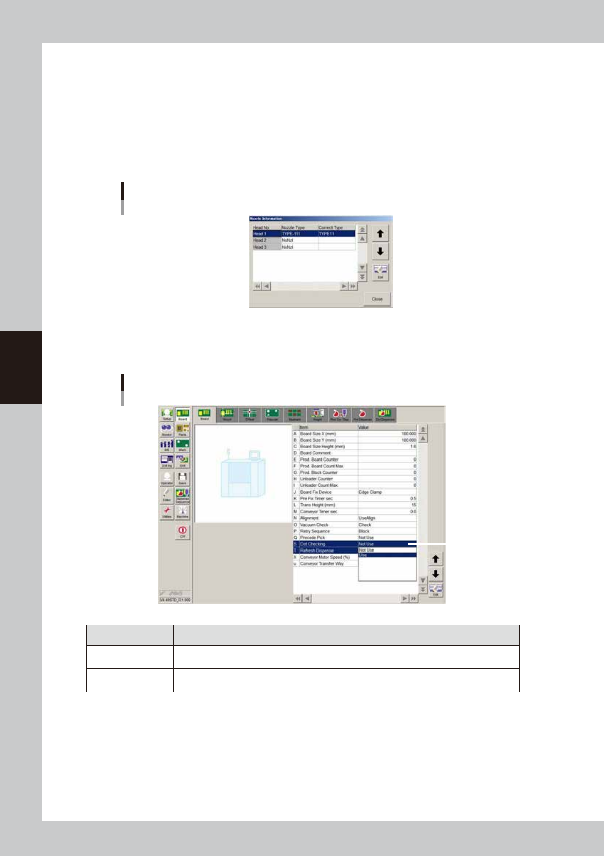
3.1.1 Enabling each setting
To perform dispense correction, enable the settings for correction type, dispense check, and correction amount
check in the nozzle information. First select the board data and then make the settings.
1
Select the correction type for each head.
1. On the Setup screen, press the [Nozzle] button to open the “Nozzle Information” dialog box.
2. Select the nozzle and correction type to use.
3. Press the [Close] button to close the “Nozzle Information” dialog box.
Nozzle information
64426-N7-00
2
Set the “Dot Checking” parameter to “Use”.
Open the [Board] - [Board] screen and set “Dot Checking” to “Use”.
”Dot Checking”
Set to "Use".
64427-N7-00
Dot Checking Description
Use
When “Check” is set for the predispense parameter during predispensing, dot recognition is
performed based on the corresponding mark.
Not Use
Even when “Check” is set for the predispense parameter during predispensing, dot recognition is
not performed and only predispensing is done.