YSD_Users_E.pdf - 第69页
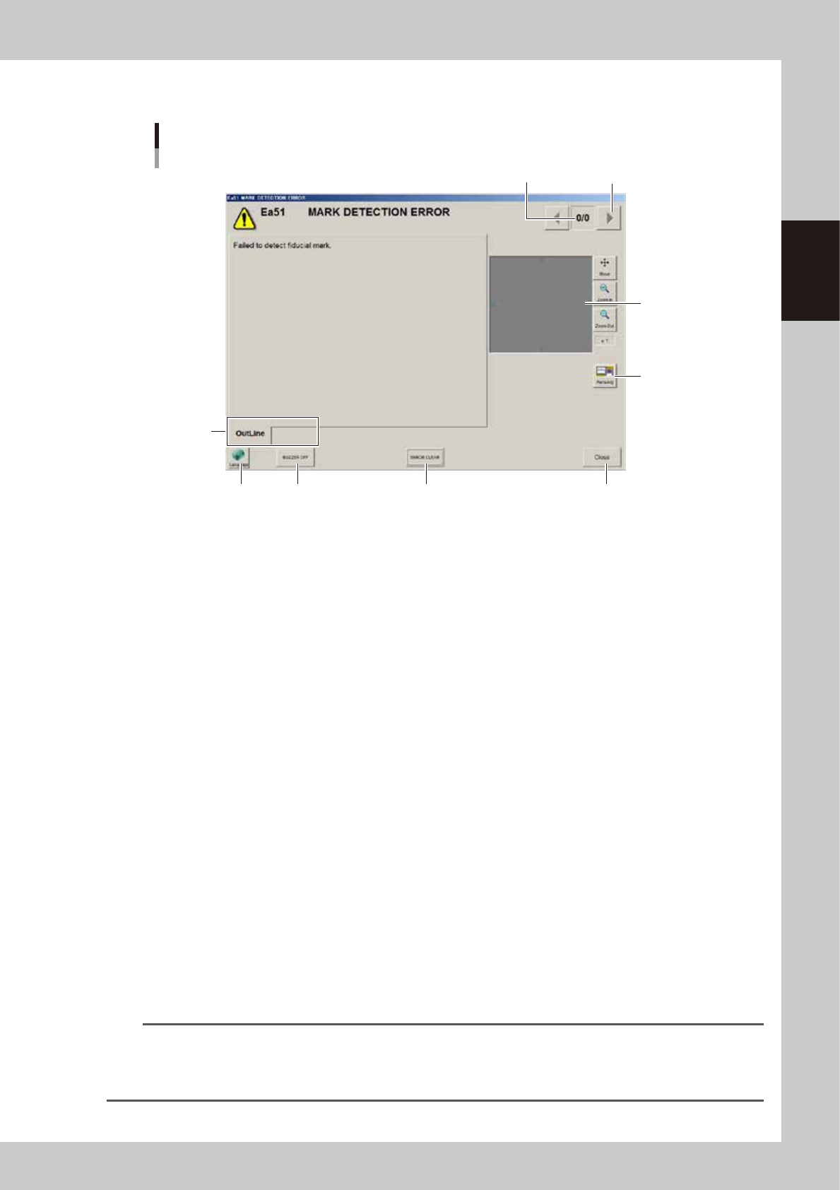
2-9 2 Basic operation n About error screen Error screen Mark detection error 1 2 3 8 6 7 4 5 [Error Switching] button (Detail) 64228-N7-00 1. Error count display Shows the currently displa yed error and the total number …
2-8
2
Basic operation
n
Various buttons and parameter input fields
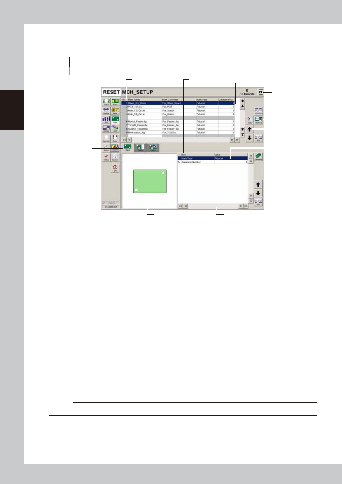
Various types of buttons, selection tabs and parameter input fields are used on the operation screen.
Operation screen example
Mark screen
1
1
2
3
4
5
6
7
Parameter listData No. list
64201-N7-00
1. Scroll bar and button (vertical and horizontal)
Use scroll bar or arrow buttons to see hidden items in the data No. list and parameter list.
2. Operation buttons
Press these buttons to open the next operation screen or dialog box.
3. Cursor up/down buttons
Use these buttons to move the cursor up or down through the data No. list and parameter list.
4. Parameter input field
Select, enter or edit parameters here. When a keyboard is used, double-click on the parameter input box to enter or edit
data.
When a touch screen (option) is used, press the [Edit] button on the lower right of the parameter list. The edit box then
pops up for data input and editing.
5. Selection tab
Select this tab to switch the parameter input screen.
6. Assistance screen
Shows an illustration or information useful for parameter input or editing. Alphabet characters shown in the parameter
list and in the illustration on this screen correspond to each other.
7. Capture button
Captures the displayed image. Captures a screen shot and saves it in a USB memory inserted into the machine’s USB port.
A “ScreenShot” folder is created in the root of the USB memory and the captured data (JPEG format) is stored in that
folder (maximum folder size is approx. 10MB), with a file name consisting of the date and time.
c
CAUTION
Always use a USB memory specified by YAMAHA to save the data.
2-9
2
Basic operation
n
About error screen
Error screen
Mark detection error
1
2
3
8
6 7
4 5
[Error Switching] button
(Detail)
64228-N7-00
1. Error count display
Shows the currently displayed error and the total number of errors. If two or more errors occurred, use the [Error
Switching] buttons (right/left arrow buttons) to switch to other error screens.
2. Message switching tab
Outline:
Displays a message for the operator.
Detail:
Displays a message for the administrator/supervisor or service personnel. This tab does not appear unless a message is
available.
3. Recognition image display (component pickup error and mark recognition error screens)
If an error has occurred in image processing during component pickup or mark recognition, the error image is displayed
here.
4. [BUZZER OFF]
Turns off the buzzer.
5. [ERROR CLEAR]
Clears the error that has occurred.
6. [Language] button
Switches the language of the message displayed on the error screen.
7. [Close] button
Closes the error screen without clearing the error.
8. [Teach] button
Opens the Teach screen. This button name differs depending on the error content. The [MarkAdj] button is displayed
instead of [Teach] when a dot recognition error has occurred.
TIP
After closing the error screen by pressing the [Close] button, you can check the locations where errors have occurred
by opening the [Monitor] - [Production] tab. Pressing the [Error Detail] button on the [Production] tab screen redisplays
the error message. For more details on the [Production] tab screen, refer to Chapter 2, "3.9 Displaying the production
monitors".
2-10
2
Basic operation
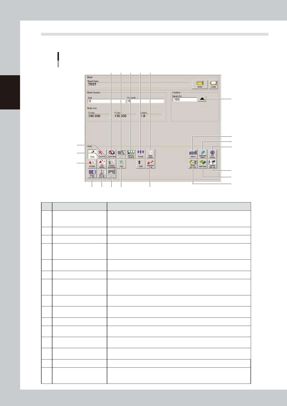
2.2 Setup screen
This section describes the operation buttons displayed on the Setup screen.
"Setup" screen
1
2
3
4
5
6
7 8
18
9 10 11
12
13
15
14
19
20
16 17
64229-N7-00
Button name Function
1 History
Saves production history data, and saves or clear any desired items of "MIS" and
"Unit log" records. Also use this button when removing a storage medium from the
machine.
2 Software Setting Sets machine screen display items, adds or deletes operators, and sets passwords.
3 Version Shows version information on application software and system.
4 System Backup
Makes a backup of machine coordinates, accuracy information, option device
information and standard coordinates necessary for machine operation or restores
the data using the backup.
5 Database
Makes a backup of parts and mark database necessary for board production or
restores the data using the backup. Also sets the database locations.
6 Board Explorer Moves, backs up, restores or copies board data.
7 Cycle Stop
Stops machine operation just after mounting components on the current board, for
example, to check the mounted results or to prevent the board from flowing to the
downstream machine.
8 Convey-out Stop
Stops machine operation after mounting components on all boards on the conveyor
and transferring them to the downstream machine.
9 Halfway Continue
After stopping the machine for some reason during operation and resetting the data,
pressing this button resumes the operation from the next dispensing position.
10 Nozzle Sets the nozzle type and correction type.
11 Temp. Setting
Specifies whether to use a heater or not and also sets the heater temperature. (Setting
range: From ambient temperature up to 50°C)
12 Cylinder exchange
When replacing a syringe, use this button to move the head to the syringe
replacement position and to perform dispensing.
13 Dot Station
This button is enabled only when a dot station (option) is used. Pressing this button
advances the paper roll of the dot station.
14 Init. Dispense After replacing a syringe, use this button to reset the liquid usage amount to “0” (zero).
15 Reset Laser
This button is enabled only when a laser displacement meter (option) is used.
Pressing this button moves the laser displacement meter to the reference
coordinates and resets the height offset value.