YSD_Users_E.pdf - 第374页
Chapter 3 Periodic maintenance items Contents 1. W eekly inspection 3-1 1.1 Checking the conveyor sensor condition and operation 3-1 1.2 Checking the board clamp condition and operation 3-2 1.2.1 Checking the board clamp…
2-3
2
Daily maintenance items
1.2 Cleaning the nozzles
The nozzle cannot function correctly if it is poorly cleaned and used while solder or adhesive is still sticking to
the nozzle tip. To prevent poor nozzle dispensing, inspect and clean each nozzle daily.
e
1
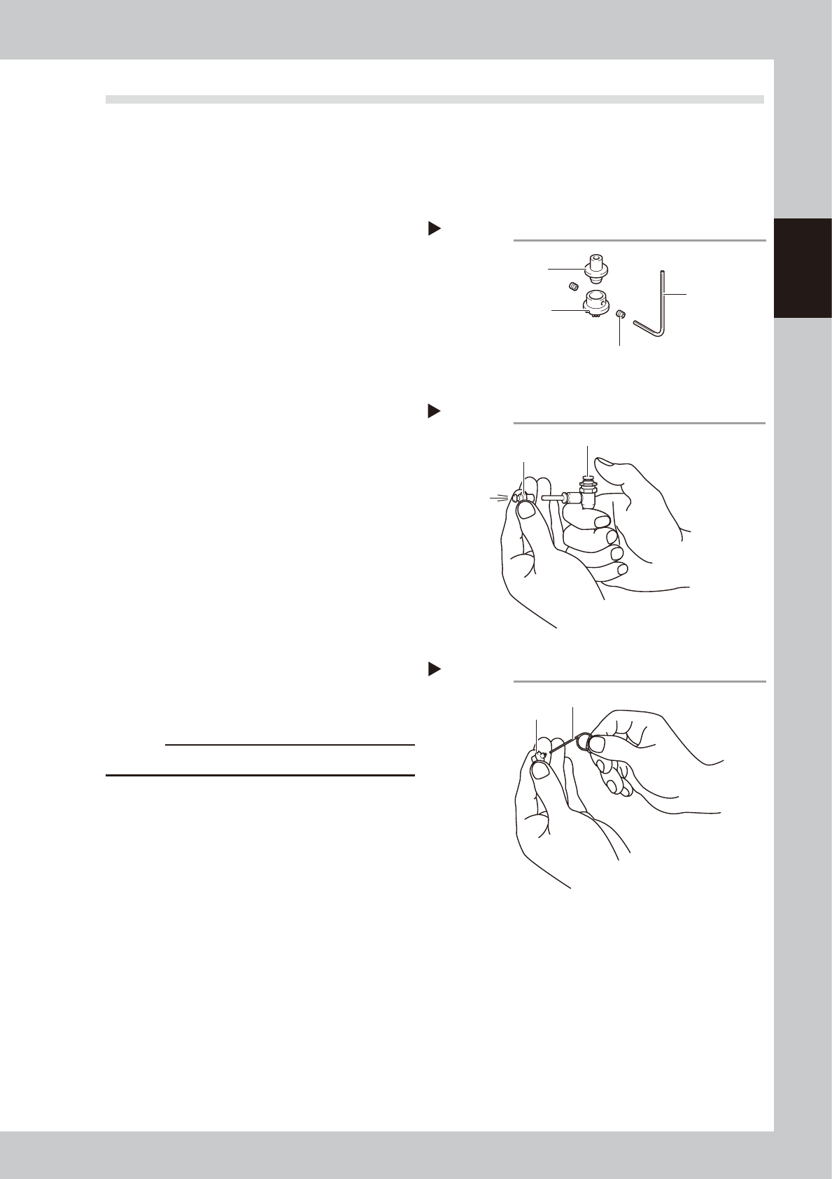
Remove the nozzle.
Always set the machine to emergency stop and open the cover before removing the nozzle.
2
Remove the dispense nozzle from
the joint nozzle.
1. Use an air blow tool to remove adhesive
and other matter from inside the nozzle.
2. Using a hex wrench, remove the dispense
nozzle from the joint nozzle.
3. Using a lint-free cleaning paper twisted
and formed in the shape of a toothpick,
wipe off adhesive and other matter
remaining inside the nozzle and joint
nozzle.
53201-N7-00
3
Remove adhesive with an air blow
tool.
1. After washing the joint nozzle with solvent
such as acetone, clean the joint nozzle
with an air blow tool.
2. Also clean the dispense nozzle using the
same procedure.
3. Using a lint-free cleaning paper twisted
and formed in the shape of a toothpick,
wipe the inside of the dispense nozzle
and joint nozzle.
53202-N7-00
4
Clean the nozzle hole.
1. Clean the nozzle hole using the cleaning
pin matching the size of the nozzle hole.
c
CAUTION
Clean carefully so as not to scratch the path.
2. Clean the nozzle hole once again with
an air blow tool.
3. Make a visual check for any adhesive
residue remaining inside the joint nozzle
and dispense nozzle holes.
53203-N7-00
n
If using an ultrasonic cleaner
• This can efficiently clean away adhesive or other
material adhering to the entire nozzle. However,
always make a visual check for any grime or other
material after cleaning.
• If a nozzle is placed in the ultrasonic cleaner solvent
without wiping away adhesive inside the nozzle, the
adhesive will react with the solvent and adhere to
the walls of the nozzle, causing nozzle clogs or
blockages.
• After cleaning the removed nozzle hole, immerse
the nozzle into a container filled with alcohol or
stored is inside a clean case, etc.
Removing the dispense nozzle
Step 2
Hex wrench
Setscrew
Dispense nozzle
Joint nozzle
Air blow into the joint nozzle
Step 3
Air blow tool
Joint nozzle
Cleaning the nozzle hole
Step 4
Cleaning pin
Dispense nozzle

Chapter 3 Periodic maintenance items
Contents
1. Weekly inspection 3-1
1.1 Checking the conveyor sensor condition and operation 3-1
1.2 Checking the board clamp condition and operation 3-2
1.2.1 Checking the board clamp condition 3-2
1.2.2 Checking the board clamp operation 3-2
2. Monthly inspection 3-3
2.1 Cleaning and greasing the X and Y axes 3-4
2.1.1 Cleaning and greasing the X-axis ball screw 3-4
2.1.2 Cleaning and greasing the X-axis guide 3-5
2.1.3 Cleaning and greasing the Y-axis ball screws 3-6
2.1.4 Cleaning and greasing the Y-axis guides 3-7
3. Six-month inspection 3-8
3.1 Cleaning the base section filter 3-8
4. One-year inspection 3-9
4.1 Cleaning and greasing the W axis 3-9
4.1.1 Cleaning and greasing the W-axis ball screws 3-9
4.1.2 Cleaning and greasing the W-axis guides 3-9
4.2 Cleaning and greasing the Z axis 3-10
4.2.1 Cleaning and greasing the Z-axis guide, ball screw and shafts 3-10
4.3 Cleaning and greasing the push-up (PU) axis 3-11
4.3.1 Cleaning and greasing he PU-axis ball screw and ball guide 3-11
4.4 Inspecting the board conveyor unit 3-12
4.4.1 Inspecting and cleaning the conveyor belt 3-12
4.4.2 Replacing the conveyor belt 3-13
4.5 Cleaning and greasing the hexagonal spline 3-14
4.6 Inspecting and cleaning the air/mist filters 3-15
4.6.1 Cleaning the filter cup 3-15
4.6.2 Cleaning the air filter and mist filter 3-16
4.7 Controller unit 3-17
4.7.1 Cleaning the filter 3-17
3-1
3
Periodic maintenance items
1. Weekly inspection
1.1 Checking the conveyor sensor condition and operation
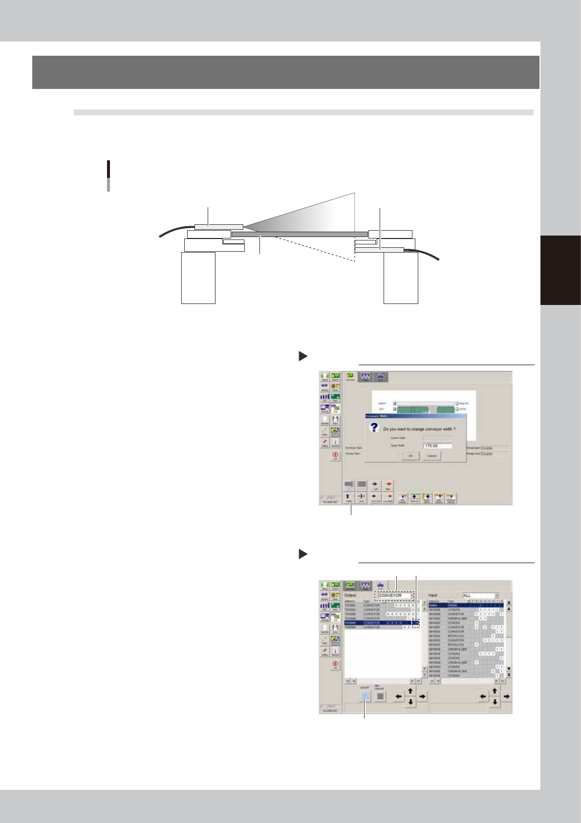
This machine uses a transmission mode fiber sensor as the conveyor sensor.
Check whether the sensor operates correctly even when the conveyor rail width is changed.
Checking the conveyor sensor condition and operation
Light emitter
Light receiver
Board
53353-N7-00
1
Open the [Unit] – [Conveyor] tab.
2
Press the [Width] button to change
the conveyor width.
In the "Conveyor Width" dialog box that
appears, enter a conveyor width and press
[OK].
The conveyor is changed to the width that
was just entered.
3
Check whether an error has
occurred.
The conveyor sensor is operating properly
unless an error message appears when the
conveyor width is changed. No further
check is necessary.
If an error message appears, then adjust the
sensor with the procedure below.
54301-N7-00
n
Adjusting the conveyor sensor
If an error occurred when the conveyor width was
changed, check the output status of the conveyor
sensor.
1. Open the [Unit] – [I/O] tab.
2. From the "Output" drop-down list, select
"CONVEYOR".
3. Select "CONV SENSOR TUNING" (T01000E) in the
output I/O list.
4. Press the [ON/OFF] button to switch the I/O status
from "0" (OFF)
→
"1" (ON)
→
"0" (OFF) to perform
auto tuning.
5. On the [Unit] – [Conveyor] tab, press the [Width]
button again and change the conveyor width. The
sensor is operating properly unless an error message
appears.
54302-N7-00
Conveyor screen
Step 2
Width button
Conveyor sensor tuning
Step 3
2 3
4