YSD_Users_E.pdf - 第83页
2-23 2 Basic operation 6 Raise the push-up plate. Check safety and press the [Push Up] button to raise the push-up plate. The boar d thickness input box then appears. Enter the thickness of the board in millimeters and p…
2-22
2
Basic operation
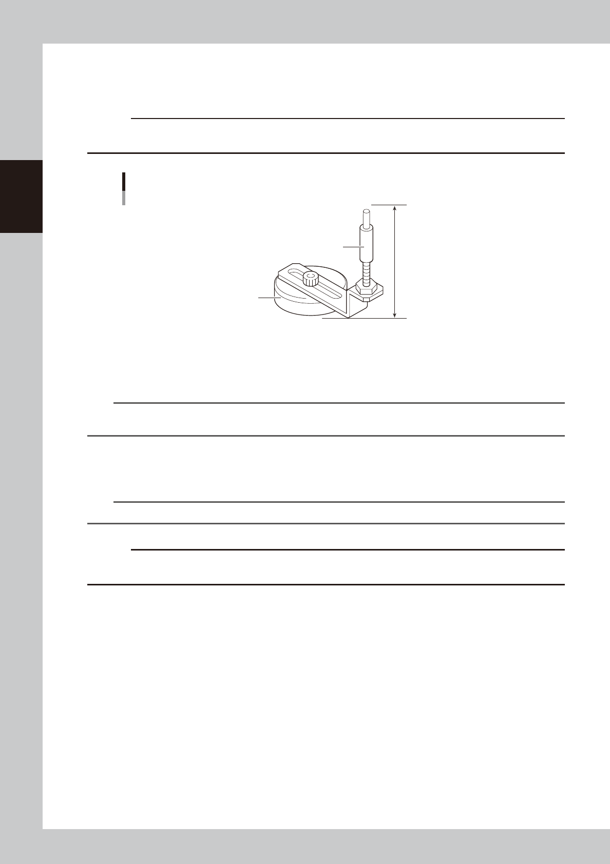
3.3.4 Arranging the push-up pins
The push-up pins are attached on the push-up plate by a magnet and used to correct downward warping of the
board.
c
CAUTION
The push-up pin height from the bottom of the magnet to the top of the pin shaft is set to 76 mm. Do not change this
height.
76mm
Support pin
Pushup pin
Magnet stand
63208-N7-00
1
Raise the push-up plate.
Check safety and press the [Push Up] button on the [Unit]–[Conveyor] tab screen. A dialog box for
board thickness input then appears. Enter the thickness of the board in millimeters and press the [OK]
button. The push-up plate will move up.
TIP
When board data has been loaded, the board thickness of the board data is displayed in the “Thickness” box in the
dialog box.
2
Place the push-up pins in the correct positions on the push-up plate.
Considering the shape and size of the board, place the push-up pins on the push-up plate so that they
uniformly support the board, including the edge of the board.
n
NOTE
Place as many push-up pins as possible on the push-up plate to support the board evenly.
c
CAUTION
Set the push-up pins in positions where they will not interfere with the conveyor rails and other parts when the push-up
plate is raised.
3
Cancel emergency stop.
Close the safety cover, release the emergency stop button, and press the [READY] button.
e
4
Set a board on the conveyor.
1. Press the [Push Up] button on the [Unit]–[Conveyor] tab screen to lower the push-up plate.
2. When the main stopper has been lowered, press the [Main Stopper] button on the [Unit]–[Conveyor]
tab screen to raise the main stopper.
3. Open the safety cover and set a board on the conveyor by placing it against the main stopper.
5
Cancel emergency stop.
Close the safety cover, release the emergency stop button, and press the [READY] button.
2-23
2
Basic operation
6
Raise the push-up plate.
Check safety and press the [Push Up] button to raise the push-up plate. The board thickness input box
then appears. Enter the thickness of the board in millimeters and press the [OK] button. The push-up
plate moves up.
e
7
Check that the board is uniformly clamped on the conveyor.
After pressing the emergency stop button, open the safety cover. Then lightly tap on the board and also
check for warping of the board from the side. If the board is supported evenly with no warping, the
adjustment is okay.
At this point, if the tips of the push-up pins do not reach the bottom of the board or the pins are pushing
the board up too much, the push-up plate height should be adjusted.
8
Check that the board is clamped securely.
Close the safety cover and press the [Board Clamp] button on the [Unit]-[Conveyor] screen to clamp
the board. Then open the safety cover, lightly tap on the board, and check for warping of the board
from the side. If the board is supported evenly with no warping, the adjustment is okay.
c
CAUTION
The board clamp moves even in emergency stop. When manually operating the board clamp, close the safety cover
so that your fingers do not get pinched.
e
9
Remove the board.
Close the safety cover, release the emergency stop button, and press the [READY] button. Then press
the [RESET] button on the operation panel to make the board unclamped. Then press the emergency
stop button, open the safety cover, and remove the board.
0
Cancel emergency stop.
Close the safety cover, release the emergency stop button, and press the [READY] button.
TIP
It may be convenient to mark the positions of the push-up pins on the plate (with a label, magic marker, etc.) for each
board type.
2-24
2
Basic operation
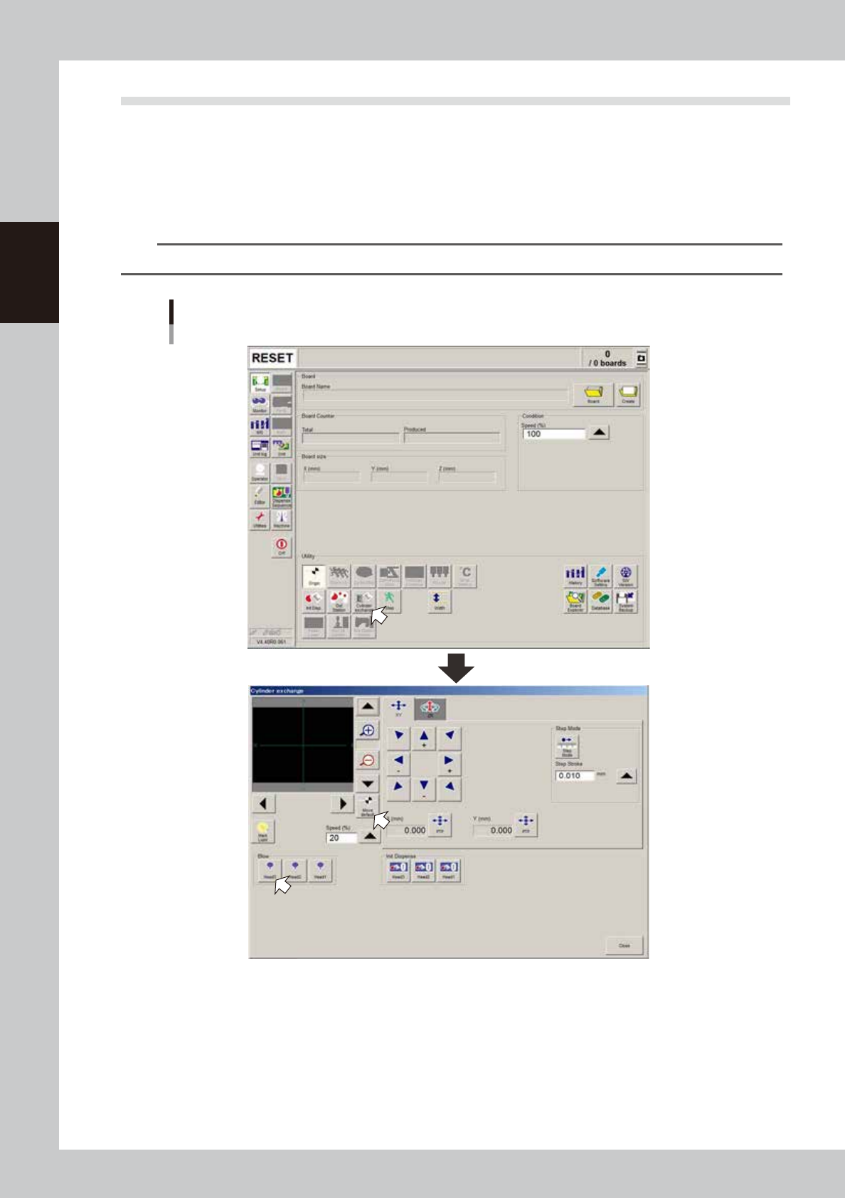
3.4 Head unit setup
This section explains how to set up the head unit and check the dispensing state.
1
Press the [Cylinder exchange] button.
The “Cylinder exchange” window appears.
2
Move the head to the syringe replacement position.
Press the [Move default] button to move the head to the syringe replacement position.
TIP
You may press the emergency stop button and then move the head by hand to the syringe replacement position.
“Move axis” window
64205-N7-00
3
Check the nozzle type.
Check that the selected nozzle type is correct for production.
e
4
Open the safety cover.
Press the emergency stop button on the operation panel to stop the servo, and then open the safety
cover.