YSD_Users_E.pdf - 第242页
5-53 5 Creating the board data 6.2 Basic parameters [Database] button 2 1 Mark Basic parameters 3 4 5 64531-N7-00 1. Mark T ype Select the mark type from the dropdown list. T he item selected here will be displayed on th…
5-52
5
Creating the board data
6.1 Creating procedure
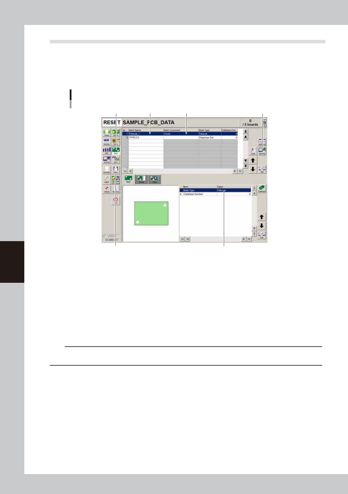
Pressing the Mark button in the menu button area opens the mark information screen as shown below. Enter
the mark name and comment in the upper grid of the screen, and set the parameters in the right lower grid as
explained below.
1
Press the [Mark] button to open the mark information screen.
Mark screen
Step 2Step 1 Step 3
Step 5
Step 4Step 7
64530-N7-00
2
Enter the mark name in the Mark Name column.
Enter a different name for each mark within 19 alphanumeric characters. A space cannot be included
in the name.
3
Enter a comment.
Type any desired comment in the Mark Comment column as necessary. You can omit entering
comments here.
4
Set the parameters.
While selecting the [Basic], [Shape], [Vision] tabs and so forth, set the necessary parameters in the right
lower grid. (See "6.2" to "6.4" in this section.)
TIP
When setting the mark parameters, it is handy to copy sample data of a mark with a similar shape from the database
and edit only the different parameters.
5
Adjust the parameters in the Parts Adjust mode.
Press the [Adjust] button to open the Parts Adjust window that allows you to adjust or check the
parameters of the selected component. (For more details, see “6.5 Mark Adjust mode” in this chapter.)
6
Repeat the above steps for other marks.
Repeat the same procedure from step 2 to register all marks to be used.
7
Save the data.
Press the [Save] button to store the data.
5-53
5
Creating the board data
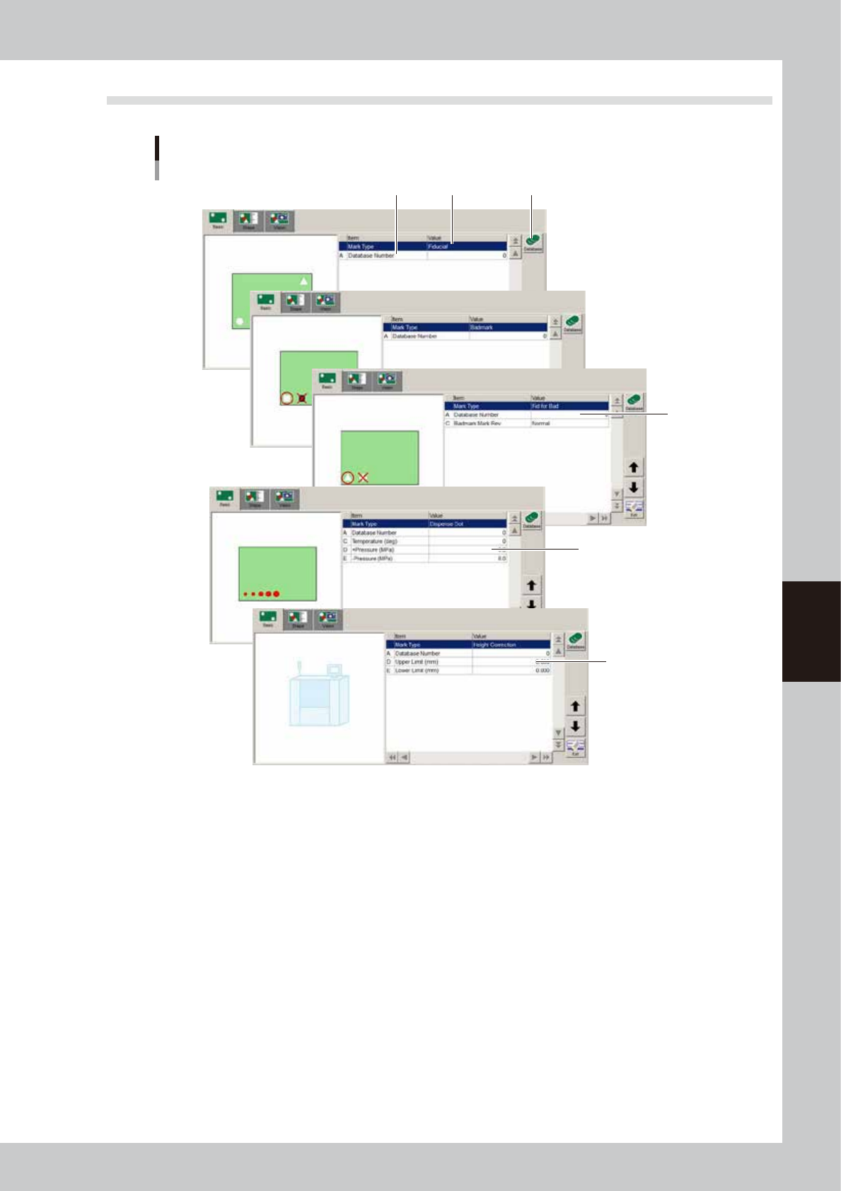
6.2 Basic parameters
[Database] button
2 1
Mark
Basic parameters
3
4
5
64531-N7-00
1. Mark Type
Select the mark type from the dropdown list.
The item selected here will be displayed on the Mark Type column in the upper grid.
2. Database Number
Shows the database number when the parameter values were copied from the database.
When you want to copy the parameter values from the database, press the [Database] button to open the database list.
Then select the copy source data and press the [Set] button to make a copy.
3. Badmark Mark Rev
Select “Normal” or “Reverse”. When “Normal” is selected, the machine continues operation as long as no badmark is
detected. When “Reverse” is selected, the machine performs work when a badmark is detected.
4. Temperature, +Pressure, -Pressure
Use these fields to make a note.
5. Upper Limit, Lower Limit
Set the upper and lower limits of the range in which the measurement result is effective. Enter these limits in millimeters.
The downward direction is positive (+) and the upward direction is negative (-), just as with the head coordinate system.
5-54
5
Creating the board data
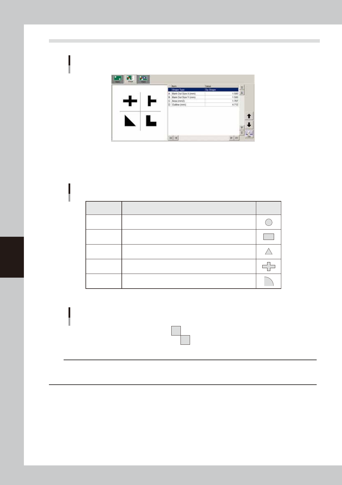
6.3 Shape parameters
Shape parameters
64533-N7-00
Shape Type
The Shape Type can be selected from the following 5 types.
From the drop-down list, select the type that matches the mark being used.
Setting Description Example
Circle
Square
Triangle
Sp. Shape
Corner
Select to detect a circular mark.
Select to detect a square mark.
Select to detect an equilateral triangular mark.
Select to detect a special mark other than above.
Select to detect a corner of a pattern as a mark.
Shape Type settings
63537-N7-00
Example of special mark
63538-N7-00
TIP
If you use a special mark composed of two or more objects, set the Algorithm Type parameter (described later) to
“Pattern”. In this case, the “Shape” parameter is ignored during recognition, so you can set this parameter to any
type. (For more details, see “6.6 Pattern matching” in this chapter.)