YSD_Users_E.pdf - 第80页
2-20 2 Basic operation 3.3.2 Changing the conveyor width First adjust the con veyor width to matc h the board width to be produced. 1 Open the [Unit]-[C onv ey or] tab screen. [Unit] - [Conveyor] screen [Width] button. 6…
2-19
2
Basic operation
3.3 Changing the conveyor unit setup
When the board type to be produced is changed, the conveyor unit must be set up correctly according to that
board type. This section describes how to change the conveyor unit setups.
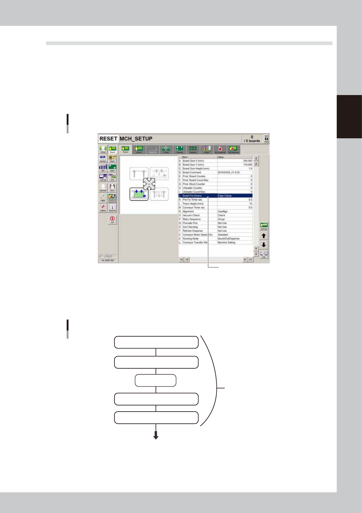
Board clamping method
The board clamping method should be set to "Edge Clamp". Open the [Board] - [Board] tab and make sure that the
"Board Fix Device" parameter is set to "Edge Clamp". If not, set it to "Edge Clamp". With this method, the board is
clamped with support from the edges and also with push-up pins.
[Board] tab grid showing Board clamping method
Board clamping method
64209-N7-00
3.3.1 Conveyor unit setup flow
The flow chart below shows the sequence for setting up the conveyor unit. The method for adjusting each
conveyor unit is described in the following sections.
Flow chart for changing the conveyor unit setups
Adjust conveyor width
Press emergency
stop button
Raise main stopper
Adjust board hold plate positoins as needed
Arrange push-up pins on push-up plate
Conveyor unit setups
Next step (head unit setup)
63206-N7-10
2-20
2
Basic operation
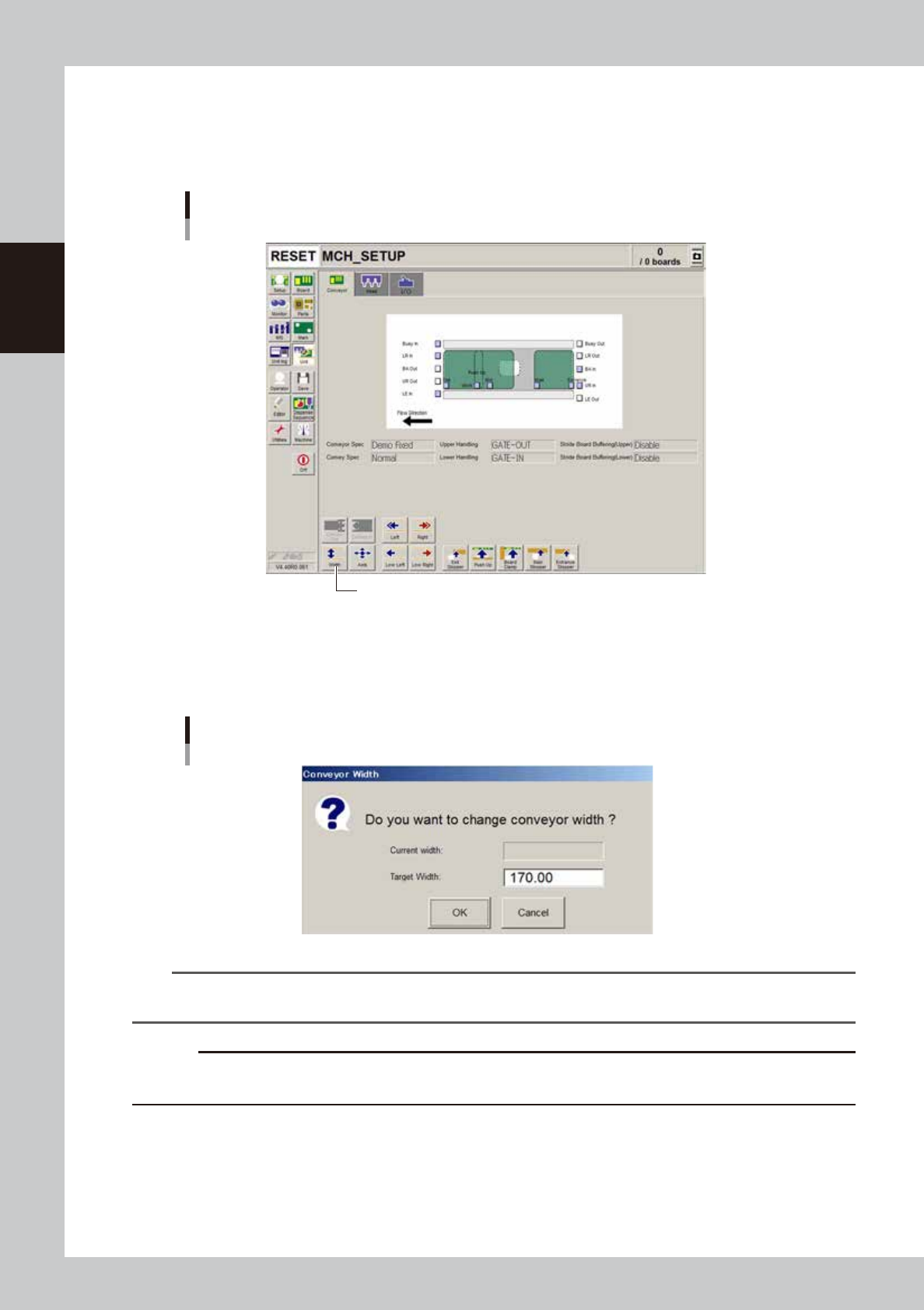
3.3.2 Changing the conveyor width
First adjust the conveyor width to match the board width to be produced.
1
Open the [Unit]-[Conveyor] tab screen.
[Unit] - [Conveyor] screen
[Width] button.
64210-N7-A0
3
Press the [Width] button.
The Conveyor Width dialog box appears. Check the conveyor width and press the [OK] button. The
conveyor rail automatically changes to the specified width.
Conveyor Width dialog box
64211-N7-00
TIP
When board data has been loaded, the conveyor width of the board data is displayed in the “Target Width” box in
the dialog box.
c
CAUTION
When push-up pins are set on the push-up plate, make sure that they do not touch the conveyor rail while adjusting
the conveyor width.
2-21
2
Basic operation
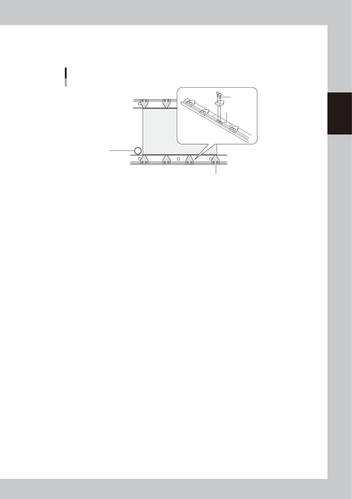
3.3.3 Adjusting the board hold plates
The board hold plates hold the edges of a board from above when the board is clamped. Adjust the positions of
the board hold plates as needed. Each plate is installed with M3 screws on the conveyor rails.
PCB
Board hold plates
M3 screw
Movable conveyor rail side
Fixed conveyor rail side
Board hold plate
M3 nut
Main stopper
63207-N7-00
1
Raise the main stopper.
On the [Unit]–[Conveyor] tab screen, press the [Main Stopper] button to raise the main stopper.
e
2
Place the machine in emergency stop.
Press the emergency stop button on the operation panel to turn off the servo.
3
Set a board on the conveyor.
Open the safety cover and set a board on the conveyor by placing it against the main stopper.
4
Adjust the positions of the board hold plates.
Loosen the screws with a screwdriver and adjust the positions of the board hold plates to match the
board size.
5
Cancel emergency stop.
Close the safety cover, release the emergency stop button, and press the [READY] button.