YSD_Users_E.pdf - 第94页
2-34 2 Basic operation 3.8 Star ting board production Start operation. 1. Check safety and press the [ST ART] button on the operation panel. When the position correction dispense function is used, after pressing the [Dis…
2-33
2
Basic operation
3
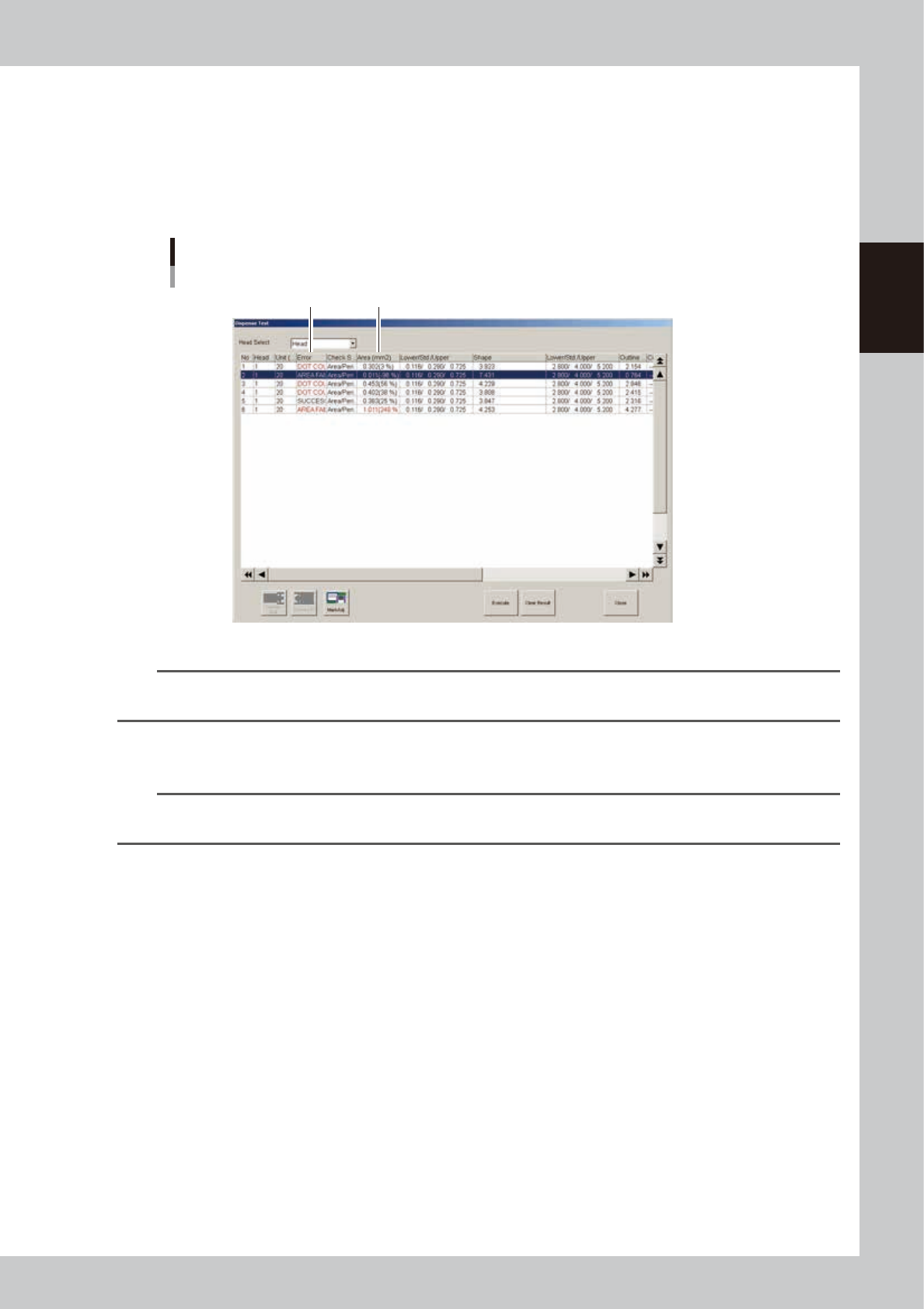
Check the test results and adjust the air pressure.
Check that the “Error” column shows “Success”. When an error is issued, check the dispensing state. If
the dispensed amount is low, the air pressure should be increased so that the test result will be
“Success”. To adjust the air pressure, check the percentage values in the “Area (mm2)” column. Raise
the air pressure for a minus value or lower the air pressure for a plus value. After adjusting the air
pressure, press the [Execute] button again to perform a dispensing test. Check the test results and adjust
the air pressure as needed until the percentage values are within ±20%.
Dispense test results
Error
Area (mm
2
)
64238-N7-00
n
NOTE
The “A: Check Shape” parameter in the [Mark]-[Shape] information should be set to “Area/Peri.”. In this case, an error
will be issued when “D: Area Tol. (%)” or “E: Shape Tol. (%)” with respect to “B: Std. Area (mm2)” is exceeded.
4
Finish the task.
Press the [Close] button to close the “Dispense Test” window.
TIP
To check the dispensing state with the camera, specify the head from the “Head Select” drop-down list, select the
dispensing No. you want to view, and press the [Mark Adj] button.
2-34
2
Basic operation
3.8 Starting board production
Start operation.
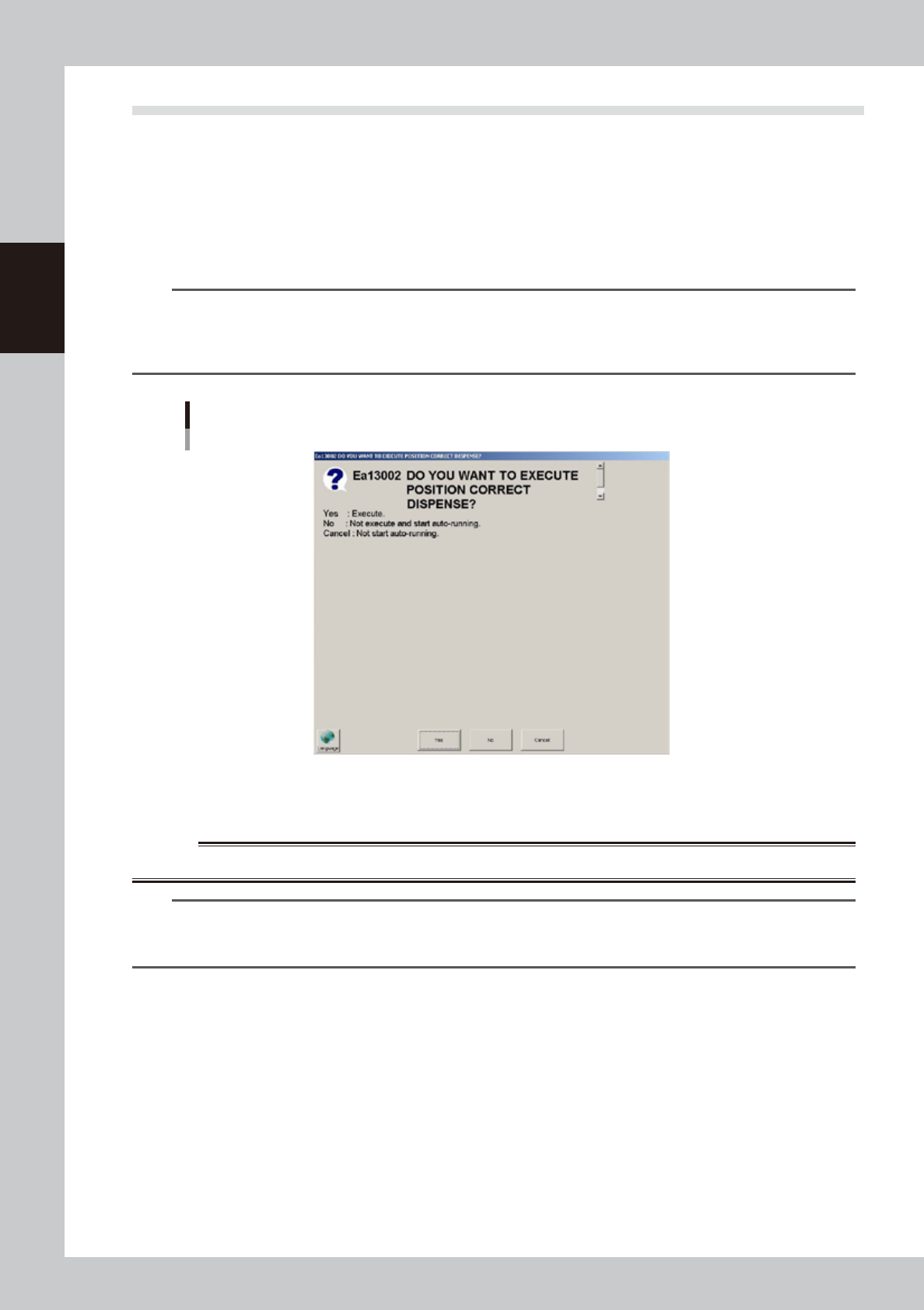
1. Check safety and press the [START] button on the operation panel.
When the position correction dispense function is used, after pressing the [Dispense] button in the
“Cylinder exchange” window or the [Blow] button on the [Unit]-[Head] tab, pressing the [START]
button displays a dialog box for correcting the dispensing positions.
If a nozzle has been detached and reattached, press the [Yes] button. If not, press the [No] button.
For detailed information, see “4. Position correction dispense function” in Chapter 4.
TIP
Dispensing for position correction is automatically performed when starting production immediately after power is
turned on. So in this case, the dialog box for correcting the dispensing positions does not appear even when the
[START] button is pressed. The dialog box may appear after the board data is changed or the safety cover is opened/
closed, although depending on the setting.
Dialog for position correction dispense
64239-N7-00
2. When the entrance sensor detects the board, the conveyor belt will start rotation. The board will be
transferred to the work position, and dispensing operation will start.
w
WARNING
NEVER ENTER THE MOVABLE AREA OF THE HEAD WHILE THE GREEN LAMP IS LIT (MACHINE IS IN AUTOMATIC OPERATION).
TIP
Operation will not start until the target syringe temperature is reached.
Whether the target syringe temperature is reached can be checked on the [Unit]-[Head] tab. After the temperature
rises to the target temperature, press the [START] button on the operation panel to start production.
2-35
2
Basic operation
3.9 Displaying the production monitors
Press the [Monitor] button to confirm the operation status during production.
Production information can be confirmed by selecting the [Production], [Main], [Detail], [Vision], [Dispense],
[Fiducial] and [Badmark] tabs.
n
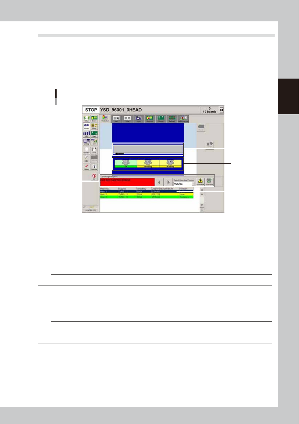
Monitor: Production
The [Monitor]-[Production] tab screen graphically shows the real-time machine status during production. When an error
occurs in the machine, opening this screen allows you to check the error and corrective action and also the warning status.
Monitor
Production
1
2
3
4
64216-N5-00
1. Conveyor status display area
If an error, operating instructions or warning regarding the conveyor occur, they will be displayed here.
If a safety sensor is responding, the board where an error has occurred is shown in semi-transparent red.
If the board clamp position sensor or board standby position sensor is responding, the board in the clamp position or
standby position is shown in semi-transparent green.
2. Head status display area
Displays the current status of the heads. The number where an error has occurred is shown in a different color.
TIP
If an error occurs in the entire machine, the background in the entire area is shown in blue.
3. Operating Navigation display area
• Select Operative Position
If an error, instructions or warning occur, this dropdown list allows you to select the position where the error is not
cleared. Only the positions where corrective action is needed are displayed here.
TIP
On the graphic layout, clicking the area where an error has occurred allows you to select the position to take
corrective action. However, the positions where no error, instructions or warning have occurred cannot be selected
by clicking on them.
• Operating instructions
Shows the corrective action for the error that is not cleared, instructions or warning regarding the positions that are listed
in the “Select Operative Position” dropdown list. If two or more errors have occurred, the corrective actions are shown in
order of priority from the one with the highest priority.
Use the left/right arrow buttons to switch to other instructions.
[Error Detail] button
Pressing this button displays an error message dialog that shows detailed information and corrective action for the error,
operating instructions or warning listed in the “Select Operative Position” dropdown list.