YSD_Users_E.pdf - 第68页
2-8 2 Basic operation n V arious buttons and parameter input fields V arious types of buttons, selection tabs and parameter input fields are used on the operation screen. Operation screen example Mark screen 1 1 2 3 4 5 …
2-7
2
Basic operation
2. Operation screen and buttons
The basic configuration and operation methods of the software screens are explained in this section. Please
read through this section before operating the machine.
n
NOTE
Because standard specification systems have no keyboard or mouse, all operations are performed from the touch-
panel. A dialog box displays at parameter input operations, and the desired operations and inputs can then be
performed with the touch-pen.
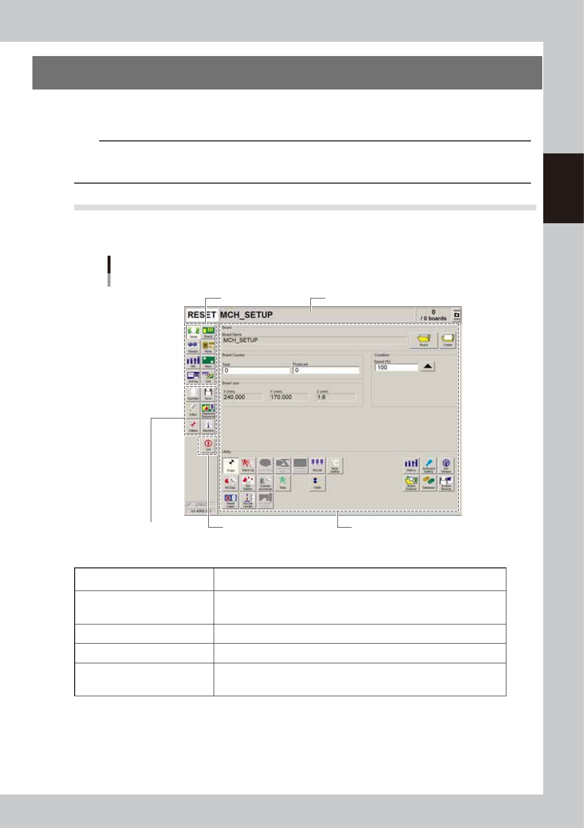
2.1 Basic configuration of operation screen
The operation screen can be divided into the "Status area", "Main menu button area" and "Submenu button and
parameter area" as shown below.
Operation screen basic configuration
Setup screen
Main menu button area 1
Main menu button area 2
Status area
Submenu button and parameter areaa
Main menu button area 3
64200-N7-10
n
Screen areas
Status area
Displays the current machine status on the left end, the selected board name in the
middle and the number of boards that have been produced on the right end.
Main menu button area 1
Shows the main menu buttons used to operate the machine.
The submenu button and parameter area will change according to the selected main
menu button.
Main menu button area 2 Shows the menu buttons used to call up auxiliary functions of the machine.
Main menu button area 3 Shows the [Off] button to turn off the machine.
Submenu button and parameter area
Displays the submenu buttons and parameters for machine operation and data
setting.
This area will change according to the selected main menu button.
2-8
2
Basic operation
n
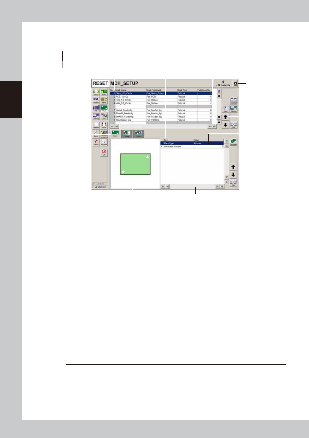
Various buttons and parameter input fields
Various types of buttons, selection tabs and parameter input fields are used on the operation screen.
Operation screen example
Mark screen
1
1
2
3
4
5
6
7
Parameter listData No. list
64201-N7-00
1. Scroll bar and button (vertical and horizontal)
Use scroll bar or arrow buttons to see hidden items in the data No. list and parameter list.
2. Operation buttons
Press these buttons to open the next operation screen or dialog box.
3. Cursor up/down buttons
Use these buttons to move the cursor up or down through the data No. list and parameter list.
4. Parameter input field
Select, enter or edit parameters here. When a keyboard is used, double-click on the parameter input box to enter or edit
data.
When a touch screen (option) is used, press the [Edit] button on the lower right of the parameter list. The edit box then
pops up for data input and editing.
5. Selection tab
Select this tab to switch the parameter input screen.
6. Assistance screen
Shows an illustration or information useful for parameter input or editing. Alphabet characters shown in the parameter
list and in the illustration on this screen correspond to each other.
7. Capture button
Captures the displayed image. Captures a screen shot and saves it in a USB memory inserted into the machine’s USB port.
A “ScreenShot” folder is created in the root of the USB memory and the captured data (JPEG format) is stored in that
folder (maximum folder size is approx. 10MB), with a file name consisting of the date and time.
c
CAUTION
Always use a USB memory specified by YAMAHA to save the data.
2-9
2
Basic operation
n
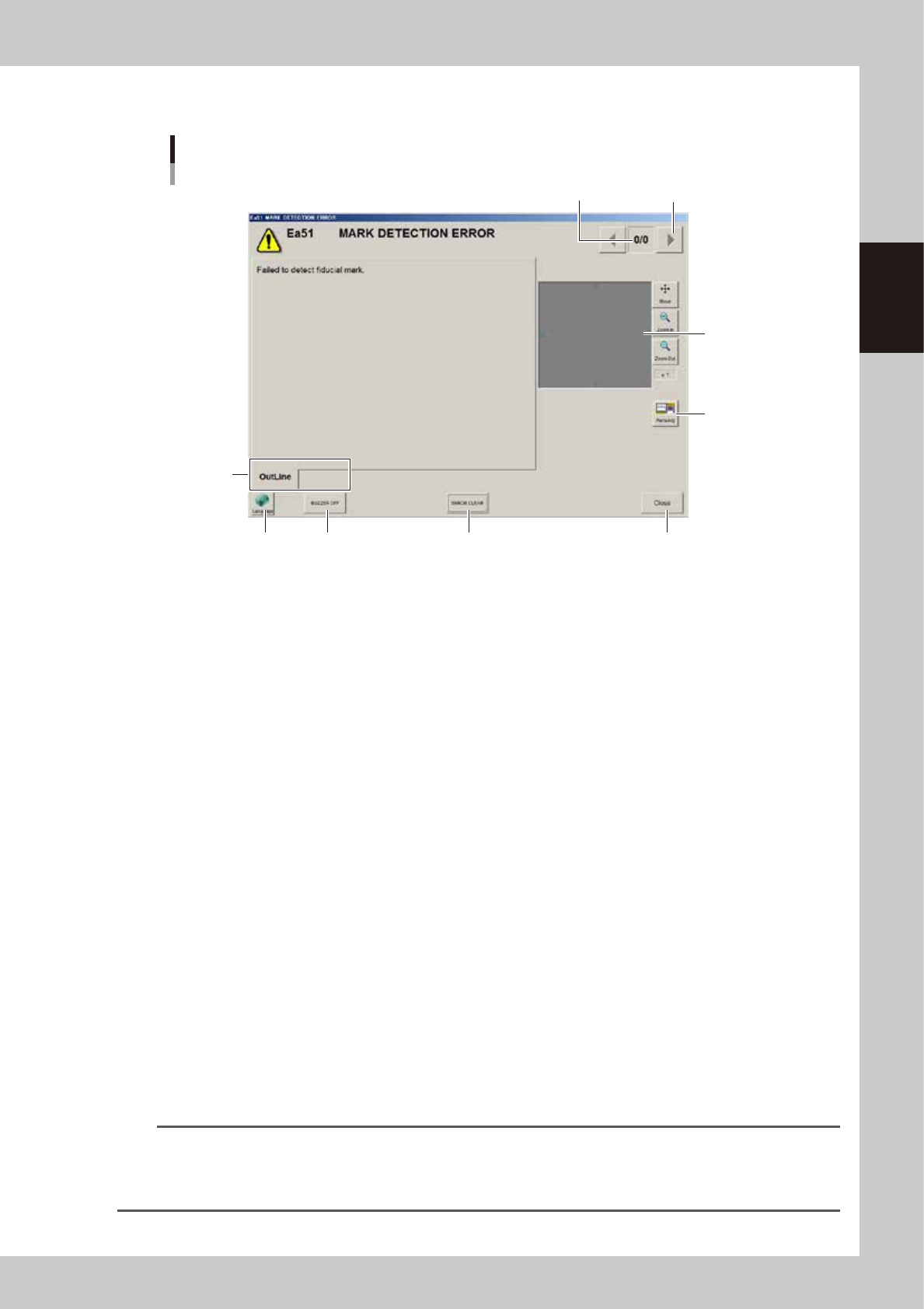
About error screen
Error screen
Mark detection error
1
2
3
8
6 7
4 5
[Error Switching] button
(Detail)
64228-N7-00
1. Error count display
Shows the currently displayed error and the total number of errors. If two or more errors occurred, use the [Error
Switching] buttons (right/left arrow buttons) to switch to other error screens.
2. Message switching tab
Outline:
Displays a message for the operator.
Detail:
Displays a message for the administrator/supervisor or service personnel. This tab does not appear unless a message is
available.
3. Recognition image display (component pickup error and mark recognition error screens)
If an error has occurred in image processing during component pickup or mark recognition, the error image is displayed
here.
4. [BUZZER OFF]
Turns off the buzzer.
5. [ERROR CLEAR]
Clears the error that has occurred.
6. [Language] button
Switches the language of the message displayed on the error screen.
7. [Close] button
Closes the error screen without clearing the error.
8. [Teach] button
Opens the Teach screen. This button name differs depending on the error content. The [MarkAdj] button is displayed
instead of [Teach] when a dot recognition error has occurred.
TIP
After closing the error screen by pressing the [Close] button, you can check the locations where errors have occurred
by opening the [Monitor] - [Production] tab. Pressing the [Error Detail] button on the [Production] tab screen redisplays
the error message. For more details on the [Production] tab screen, refer to Chapter 2, "3.9 Displaying the production
monitors".