YSD_Users_E.pdf - 第186页
4-58 4 Making the dispensing stable 4 Check dispense positions. 1. Press the [Trace] button. 2. The camera moves to the selected dispense position. Check that the center cursor in the vision monitor is located at the cen…
4-57
4
Making the dispensing stable
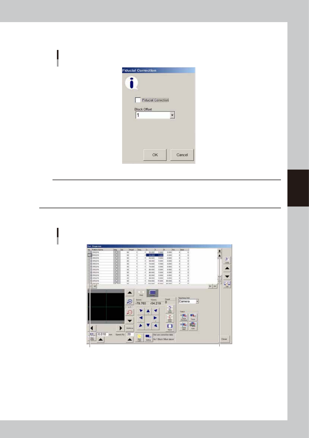
3. If the board data uses fiducial correction, select the [Fiducial Correction] check box in the dialog
box.
Fiducial correction setting
64455-N7-00
n
Note
When you correct, add or create the board data using fiducial marks, selecting the "Fiducial Correction" check box
allows the machine to recognize fiducial marks on the board so that corrected dispense data is automatically
obtained. This makes it possible to perform accurate teaching or tracing of the specified position. To use this function,
the fiducial mark coordinates and mark data must be set correctly in advance.
3
Select the dispense No. of the position you want to check.
Selecting dispense No.
Select the dispense No. Press this until the desirewd
data row appears.
64456-N7-00
4-58
4
Making the dispensing stable
4
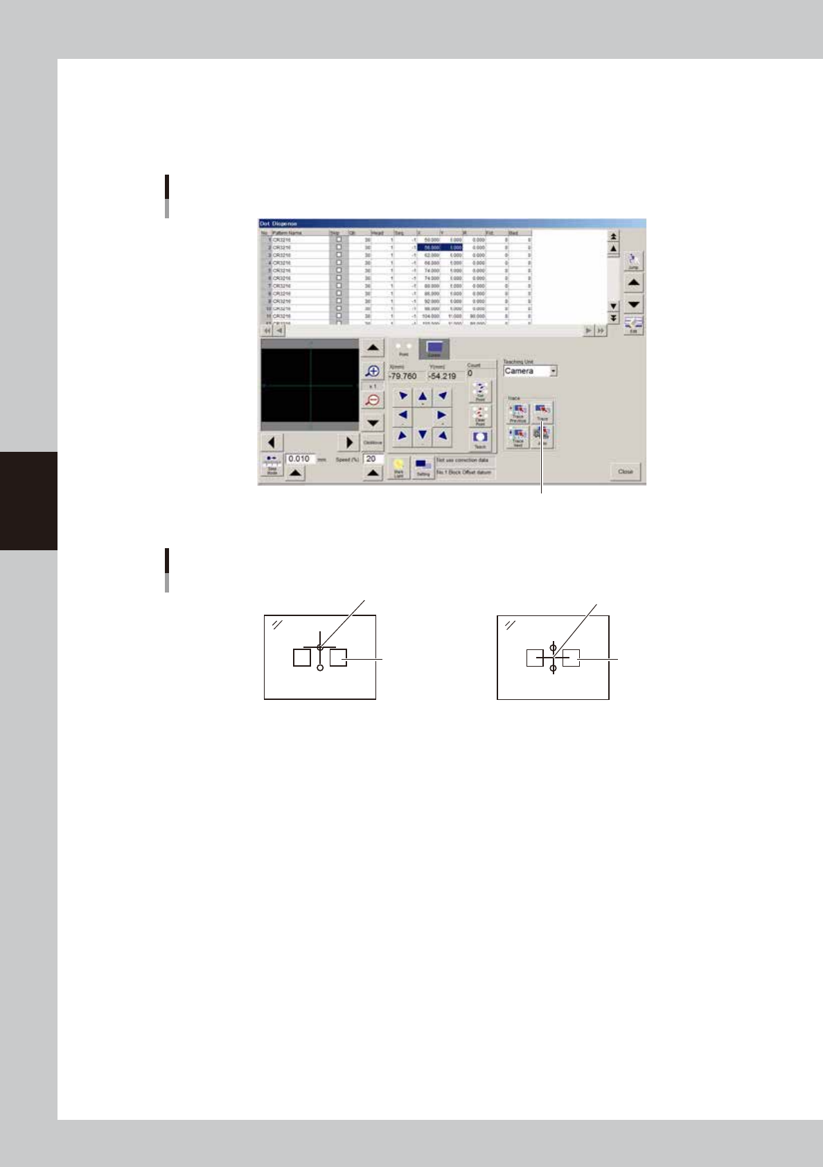
Check dispense positions.
1. Press the [Trace] button.
2. The camera moves to the selected dispense position. Check that the center cursor in the vision
monitor is located at the center of the dispense position.
[Trace] buttons
[Trace] button
64457-N7-B0
Displaying in the vision monitor
Land pattern
Center cross cursor
2-shot nozzle1-shot nozzle
Land pattern
Center cross cursor
63422-N7-00
4-59
4
Making the dispensing stable
5
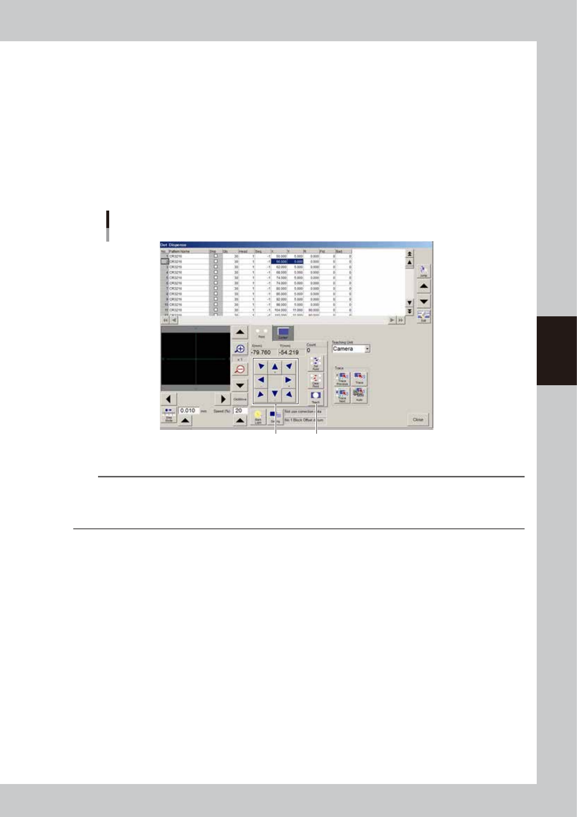
Correct the XY data.
If the center cursor in the vision monitor is off center of the dispense position, correct the XY data.
Two kinds of correction methods are available: by entering values directly and by teaching.
Correcting by entering values directly
In the vision monitor, find how much correction is required in the X and Y directions, and then enter the
necessary X and Y values.
Correcting by teaching
Proceed as follows.
1. Using the [move camera] buttons (arrow buttons), move the camera to locate the center cursor in
the vision monitor to the center of the dispense position.
2. Press the [Teach] button. The coordinate data will be updated to match the camera position.
Teaching
Use these arrow buttons
to move the camera.
[Teach] button
64458-N7-C0
TIP
If all the dispense positions at a certain angle are off for a certain head, make adjustments using "Precision Zigzag"
parameter.
For instance, if all the 90-degree dispense positions in Y direction for head 1 are 0.08 mm off, subtract 0.08 from the
"Precision Zigzag" parameter (Head 1: 90° Y(mm)) and enter the result.
6
Check the land pattern name.
Check whether the component names (e.g. R23, U12) printed on the board matches the land pattern
name registered in the dot dispense information. If the name has not been entered, enter it now. If the
component names printed on the board are not within the camera's view field, use the [move camera]
buttons (arrow buttons) to adjust the camera position.