YSD_Users_E.pdf - 第54页
1-14 1 Part names and functions 6. Axis configuration The following describes the configuration of ser vo-controlled axes and their operating direction. Axis configuration and plus/minus directions Head unit R axis Y axi…
1-13
1
Part names and functions
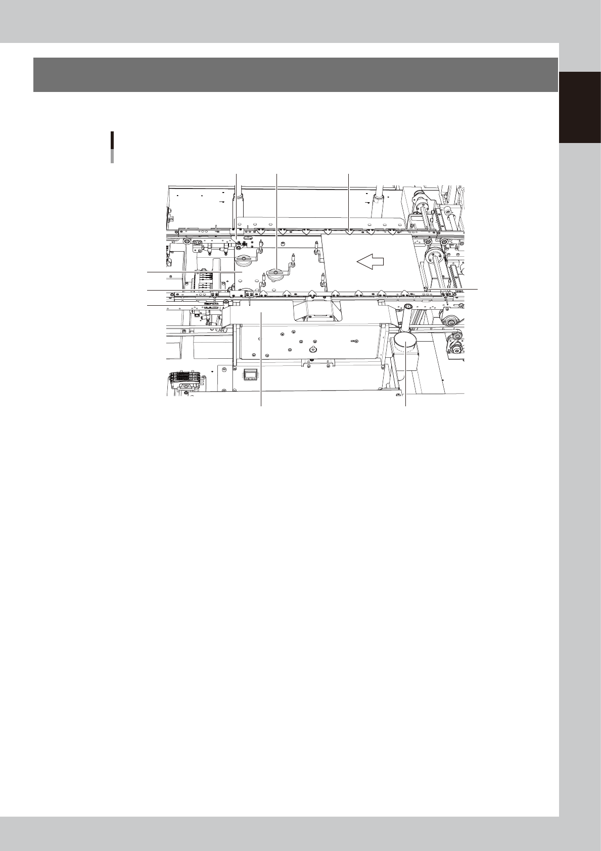
5. Conveyor unit
The conveyor unit used to clamp a board consists of the following devices.
5
6
Board
3
2
1
7
4
8
9
Conveyor unit
63112-N7-00
1. Main stopper
When a board is carried in on the conveyor, the main stopper halts travel of the board in the work position.
2. Push-up plate
The push-up plate clamps the board up against the conveyor rails, with the push-up pins (supporter pins) placed on the
push-up plate.
3. Push-up pins
These pins are arranged on the push-up plate and secure the board by pushing it up from the bottom.
4. Board hold plates
These plates hold the edges of the board from above when the board is clamped in the work position.
The positions can be adjusted according to the board size.
5. Board clamp
The board clamp secures the board by pushing its edges up against the board hold plates.
6. Dot station (option)
This is used as a dummy board where adhesive, etc. is predispensed.
7. Touch sensor (option)
When replacing a nozzle, this sensor is used to correct variations in the height (length).
8. Entrance stopper
(standby position stopper)
(option)
This stopper is installed at the standby position where the next production board is stopped.
9. Liquid disposal cup
This is a disposal cup used to receive liquid that may drop during replacement of a syringe. Prepare a cup of the
appropriate size.
1-14
1
Part names and functions
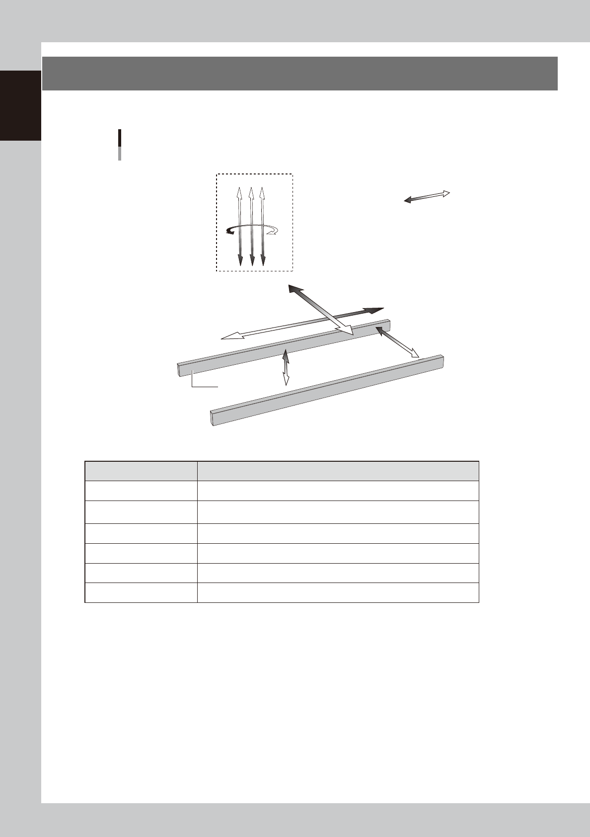
6. Axis configuration
The following describes the configuration of servo-controlled axes and their operating direction.
Axis configuration and plus/minus directions
Head unit
R axis
Y axis
X axis
W axis
PU axis
Plus direction
Minus direction
Conveyor rail
Example of triple-head unit
Z1Z2Z3
63113-N7-00
n
Function of each axis
Axis name Function
X axis Moves the head assembly in parallel with the board flow on the conveyor.
Y axis
Moves the head assembly in the direction perpendicular to the board flow on the
conveyor.
Z1 to Z3 axes Controls the height of the dispensing heads.
R axis Rotates the nozzle shafts of the dispensing heads.
W axis Adjusts the conveyor width.
PU axis Raises and lowers the push-up plate.
1-15
1
Part names and functions
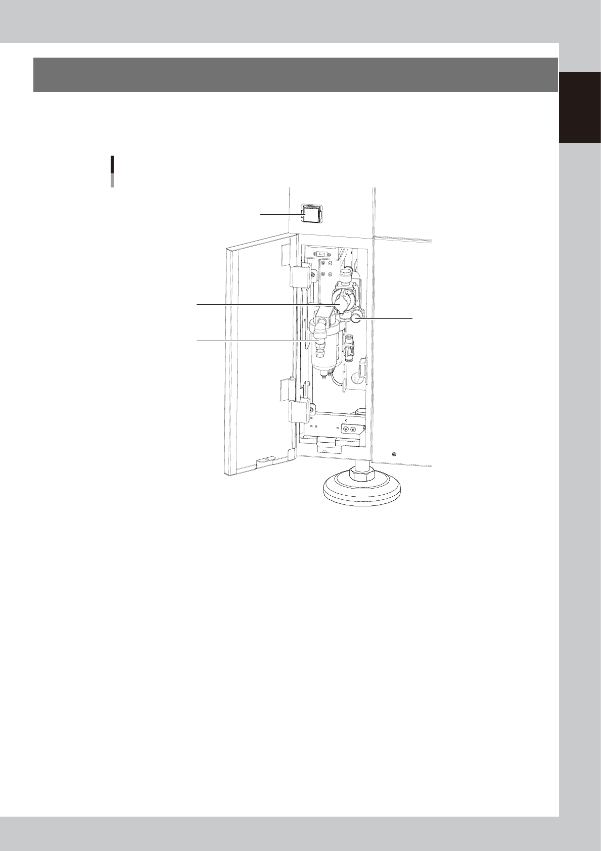
7. Air regulator unit
The air pressure regulator adjusts the pressure of compressed air supplied to the pneumatically driven
components of the machine and is located behind the front lower left panel of the machine. The air pressure
regulator must be correctly set to maintain the optimum air pressure.
Air regulator unit
Air pressure supply/
shutoff switch
Source air connector
Pressure regulator
Behind lower left panel
Air pressure gauge
63114-N7-00
• Air pressure gauge
Shows the air pressure setting (upper display) and pressure-drop detection level (lower display).
The air pressure display is green in normal condition but changes to red when a pressure drop is detected.
Supply air pressure: 0.45MPa or more
Air pressure setting: 0.40Mpa (0.40MPa to 0.41MPa)
Pressure-drop detection level: 0.33MPa
• Air pressure supply/shutoff switch
Turning this switch to the right shuts off air supply and exhausts the air that remains inside the air path of the machine.
• Pressure regulator
Use to adjust the air pressure so that air pressure gauge reads 0.4MPa (at a consumption rate of 60NL per minute).
• Source air connector
Prepare an air hose with an inner diameter of at least 8 mm having a 30SH socket (Nitto Koki, or equivalent), and
connect it to this connector. Use dry, clean air passed through an air filter.