YSD_Users_E.pdf - 第384页
3-10 3 Periodic maintenance items 4.2 Cleaning and greasing the Z axis 4.2.1 Cleaning and greasing the Z-axis guide, ball screw and shafts e 1 Mo ve the head. 1. Press the [Replace Syringe] button on the Setup screen. 2.…
3-9
3
Periodic maintenance items
4. One-year inspection
4.1 Cleaning and greasing the W axis
4.1.1 Cleaning and greasing the W-axis ball screws
1
Set the conveyor width to maximum.
Press the [Width] button on the Setup screen
to display the "Conveyor Width" dialog, and
select "Max Width".
e
2
Press the emergency stop button.
The machine must be in emergency stop to
ensure safety during work.
3
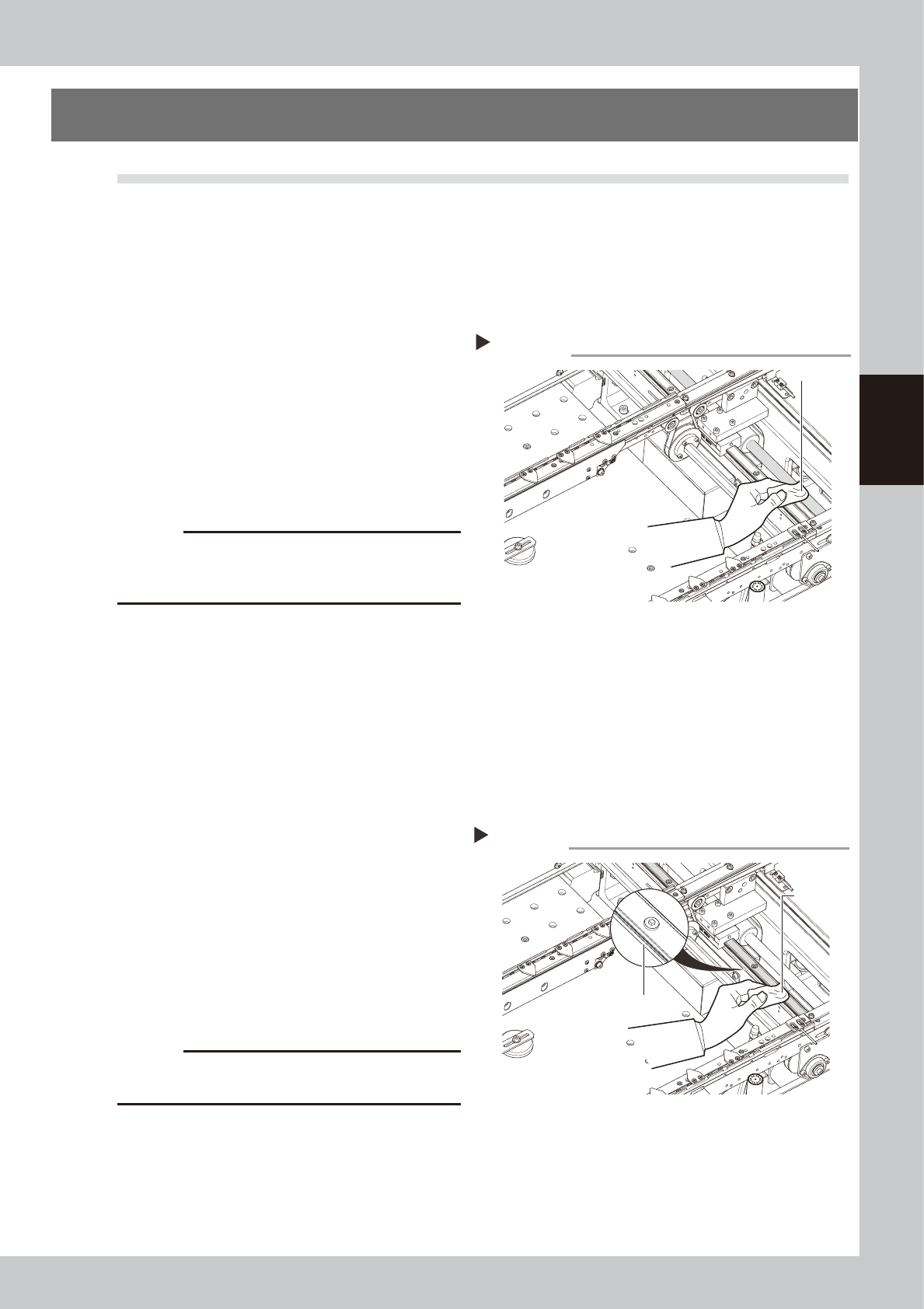
Clean the ball screws.
Wipe away the old grease and dirt from the
ball screw with a lint-free cloth or paper
towel (for clean room use).
53315-N7-00
c
CAUTION
Wipe away the old grease and dirt in the lead groove
of the ball screw. Also check that no debris or residue
remains in the lead groove.
4
Apply grease to the ball screws.
Apply the specified grease (NSL) by hand
uniformly over the surface and lead groove
of the ball screw.
4.1.2 Cleaning and greasing the W-axis guides
1
Set the conveyor width to maximum.
Press the [Width] button on the Setup screen
to display the "Conveyor Width" dialog, and
select "Max Width".
e
2
Press the emergency stop button.
The machine must be in emergency stop to
ensure safety during work.
3
Clean the linear guides.
Move the head (or conveyor rails) to one
end of its axis, and wipe away the old
grease and dirt from the linear guides with a
lint-free cloth or paper towel.
53316-N7-00
c
CAUTION
Wipe away thoroughly the old grease in the grooves of
the linear guide rails.
4
Apply new grease to the guide rails.
Apply grease (NSL) by hand to the guide
surface and groove uniformly.
Cleaning the W-axis ball screw
Step 3
Paper wipe
Cleaning the W-axis guide
Step 3
Paper wipe
Guide groove
3-10
3
Periodic maintenance items
4.2 Cleaning and greasing the Z axis
4.2.1 Cleaning and greasing the Z-axis guide, ball screw and shafts
e
1
Move the head.
1. Press the [Replace Syringe] button on the
Setup screen.
2. Press the [Move default] button.
3. Press the emergency stop button and
then open the cover.
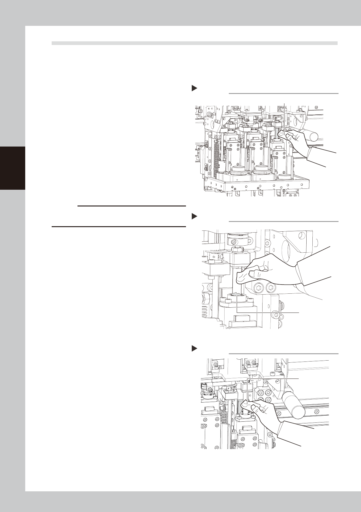
2
Clean the ball screw and spline
shafts.
Ball screw
Lower the Z axis and wipe the ball screw
with a paper wipe.
Spline shafts
Wipe the spline shaft of each head with a
paper wipe.
53317-N7-00
c
CAUTION
Wipe away the old grease and dirt in the lead groove
of the ball screw.
3
Apply grease.
Ball screws
Apply grease by hand to the entire ball
screw.
Spline shafts
Apply a thin coat of grease by hand to the
entire spline shaft of each head.
4
Wipe away excess grease.
Move the head up and down by hand a few
times and wipe away excess grease which
has collected at the nut section.
53318-N7-00
5
Clean and grease the guide.
Clean and grease the guide with the same
procedure as for the ball screw.
53328-N7-00
Cleaning the Z-axis ball screw
Step 2
Paper wipe
Wiping off grease on the Z-axis ball screw
Step 4
Excess grease
Cleaning the Z-axis guide
Step 5
Paper wipe
3-11
3
Periodic maintenance items
4.3 Cleaning and greasing the push-up (PU) axis
The push-up axis is designed to prevent warping of the board when it is clamped in the work position. It also
prevents depressing of the board during dispensing. Periodically inspect and clean the push-up axis to ensure
it operates correctly.
4.3.1 Cleaning and greasing he PU-axis ball screw and ball guide
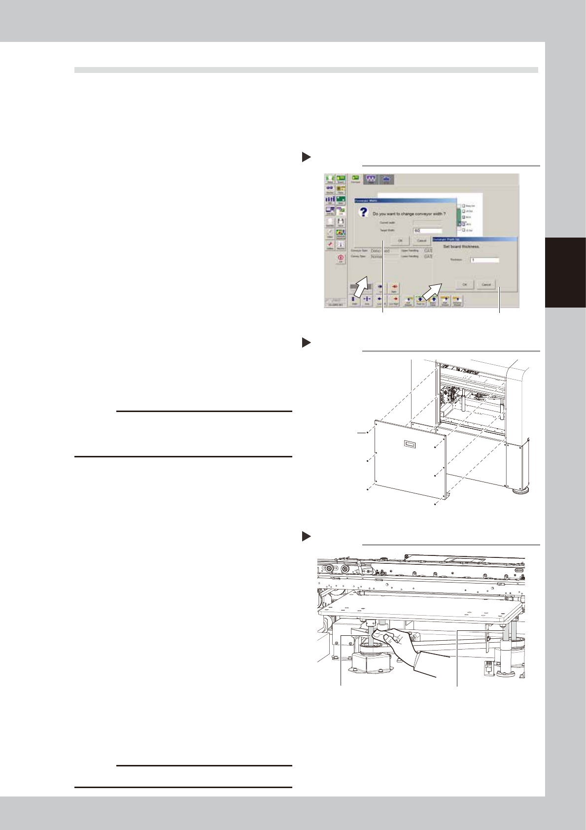
1
Set the conveyor width to minimum.
1. Remove the push-up pins attached on
the push-up plate.
2. On the Unit screen, select the [Conveyor]
tab.
3. Press the [Width] button to display the
"Conveyor Width" dialog. Enter the
minimum width from the specifications
and press the [OK] button.
2
Raise the push-up unit.
Press the [Push-up] button, enter "1", and
press the [OK] button.
54304-N7-00
e
3
Remove the rear cover.
After pressing the emergency stop button,
use a Philips screwdriver to remove the six
screws securing the rear cover.
53319-N7-00
c
CAUTION
The rear cover does not have a safety device. Always
press the emergency stop button before removing the
rear cover.
4
Remove the old grease by hand.
Using a paper wipe, wipe away the old
grease on the ball screws (2 places) and
ball guides (2 places) shown at the right.
53320-N7-00
5
Apply the new grease by hand.
Apply as much as 2 cm of new grease to
your finger, and apply it evenly into the ball
screw lead grooves and on the ball screw
guides.
6
Raise and lower the push-up unit
manually.
Cancel emergency stop, and raise and
lower the push-up unit manually several
times.
e
7
Wipe away excess grease by hand.
After pressing the emergency stop button,
wipe away excess grease by hand.
8
Reattach the rear cover.
Reattach the rear cover that was removed
in step 3.
c
CAUTION
Do not forget to reattach the rear cover.
Raising the push-up unit
Step 1, 2
Step1
Step2
Removing the rear cover
Step 3
Screws securing
the rear cover
Cleaning the PU-axis ball screw
Step 4
Ball guides (2 places)Ball screws (2 places)