YSD_Users_E.pdf - 第155页
4-27 4 Making the dispensing stable 3.1.7 Setting the calculation type T he dispensed area tends to get smaller when the liquid level in the syringe drops. Setting the calculation type allows correcting to a more accurat…
4-26
4
Making the dispensing stable
9
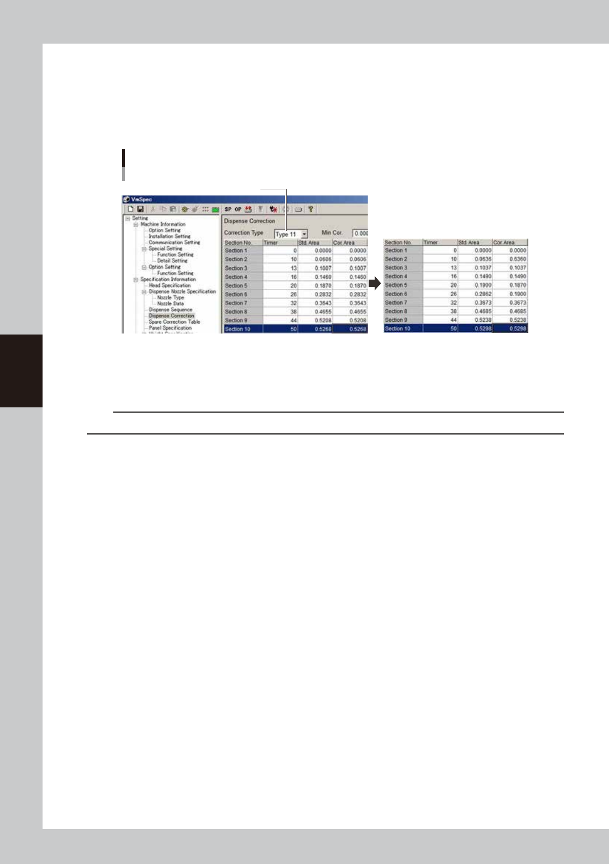
Enter the offset value in each section.
Enter the offset values so that the area at timer “20” matches the standard area. Open the [Machine]
- “Specification Information” - “Dispense Correction” screen, and set the correction type. Enter “0.1900”
for timer “20” and then enter the offset amounts for other sections.
(Example) If the standard area at timer “20” is “0.187”, then add 0.003 to that value to obtain “0.1900”
and also add “0.003” to the other areas.
Offset value setting
Select correction type
64444-N7-00
2
Reload the board data.
Save the machine data setting. Press the [Board] button and then the [Select] button to reload the
board data.
n
NOTE
After changing the machine data setting, the board data must be reloaded to enable the change.

4-27
4
Making the dispensing stable
3.1.7 Setting the calculation type
The dispensed area tends to get smaller when the liquid level in the syringe drops. Setting the calculation type
allows correcting to a more accurate dispensing area. There are two calculation types for making corrections:
proportion type and constant type. Make a graph by measuring the area of each dispensing amount with a
syringe having the liquid level from 10 to 50% and determine the calculation type. This section describes the
procedure for setting the calculation type using a Type 111 nozzle as an example.
1
Set up the head unit.
Prepare a target nozzle and syringe having a 10 to 50% liquid level and attach them to the head. If a
syringe is already attached in the previous section, then expel some liquid from the syringe until the
liquid level becomes 10 to 50%.
n
NOTE
The difference is easier to see when the liquid amount is small, making it easier to set the calculation type.
2
Bleed the nozzle air.
When setting the temperature, bleed the air after waiting until the target temperature is reached. For
the instructions on how to bleed the nozzle air, see “3.6 Bleeding the nozzle air” in Chapter 2.
3
Start the adjustment utility.
1. Press the [Utilities] button.
2. Select “Operator” and press the [OK] button.
3. Press the [Dispense Correction] button.
4-28
4
Making the dispensing stable
4
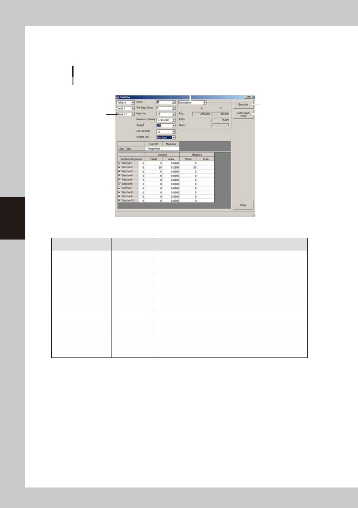
Set the parameters
For the setting of each nozzle, see “
n
Nozzle settings” in “3.1 Using the dispense correction function” in
this chapter.
Parameter setting
Example for Type 111 nozzle
Dispensing location
[Auto Input Timer] button
[Execute] button
Type
Head
64445-N7-00
n
Example of settings for Type 111 nozzle
Parameter Setting Description
Head Head 1 Select the head to use for dispensing.
Type Type 11 Select the correction number to make settings.
Num. 5 Set the number of measurement points. (5 or more)
Pre. Disp. Num. 5 Set the number of predispensing points. (3 or more)
Mark No. 11 Set the mark No. used for recognition.
Speed 100 Set the speed to “100”.
Use Section 10 Set the number of sections to be corrected. (10 is recommended)
Height Cor. Not used If a non-contact nozzle is used, set this item to “Use”.
Dispensing location Dot station Set the dispensing location.
5
Start measurements.
1. Set the air pressure equal to the pressure for new syringes, and press the [Execute] button. The paper
feed dialog box appears. Check that no dots remain and press the [OK] button.
2. On the [Monitor]-[Vision] screen, check the recognition results and press the [Yes] button while
making a note of the measurement data.
3. Repeat measurements while increasing the timer until the area of the dispensed dots reaches the
maximum area that will be obtained with a new syringe.