CM602all_EJM8AESM_Service Manual.pdf - 第1011页
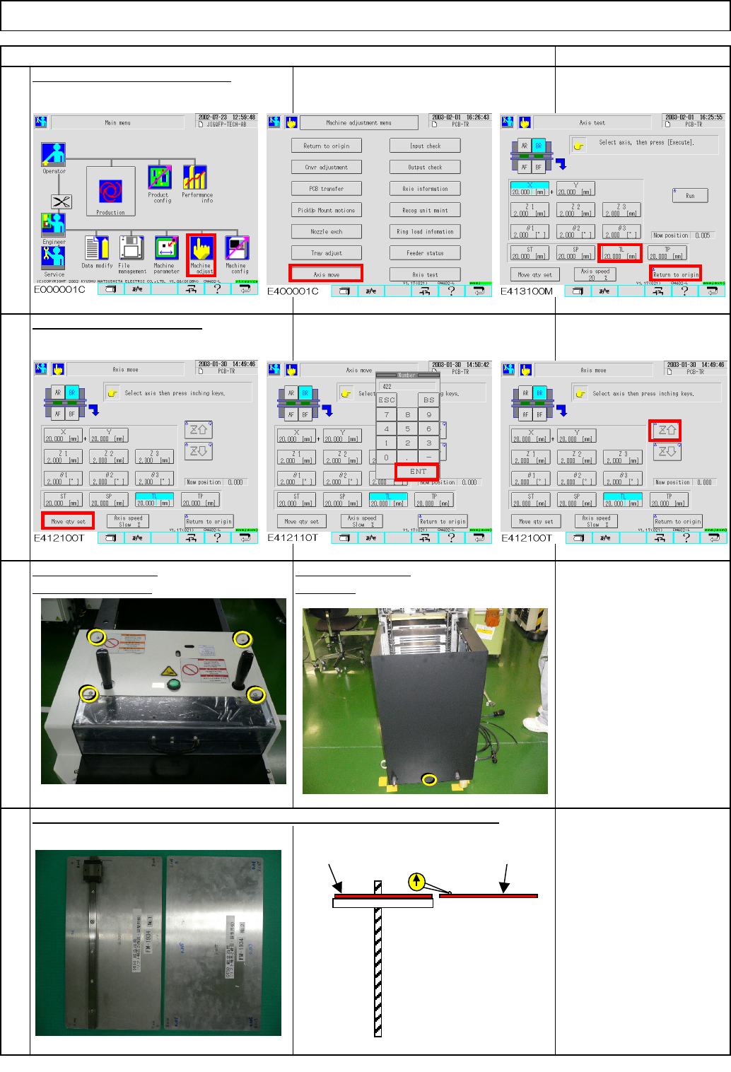
Tray Check the height of the lift table (extension section) and the supply-section table. Put the magnetic stand and a dial gauge on the lift table (extension section). Loosening the coupling lowers the lift. To avoid le…
Tray
Put the palette jig on the lift table (extension section) and the supply table.
Remark
Return the lift-axis to the origin.
Item
4
Phillips screwdriver #2
M4 screw 4 to 6 pcs.
Direct Tray
Remove the bolts.Remove the cover.
2
1
3
Raise the lift-axis 422 mm.
Jig: FM-1934
Lift-axis height check jig
Turn off the power.
Rear side
422
Lift table
Supply-
section table
Lift-axis ball screw
FM-1934
FM-1934
EJM8A-E-SMA070204-A01-00
Page 7-2-4-2
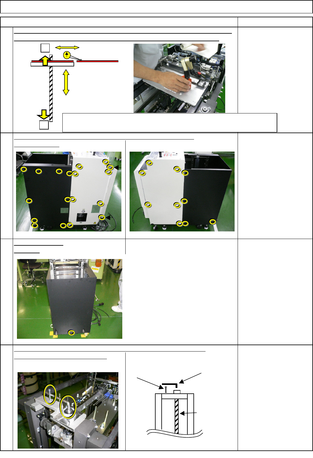
Tray
Check the height of the lift table (extension section) and the supply-section table.
Put the magnetic stand and a dial gauge on the lift table (extension section).
Loosening the coupling lowers the lift. To avoid letting the lift descend,
8
6
7
put on an Allen key and the screw.
Item
Rear side
5
Specifications:
within +/-1.0 mm
Magnetic stand
Dial gauge
Remark
Open the cover.
Direct Tray
If outside the +/-1mm, return the lift-axis to the origin (See Step 1).
Remove the bolts.
Phillips screwdriver #2
Screw M4 14 pcs.
Allen key 5 mm
Screw M4 x 40
Allen key 2.5 mm
M3 4 pcs.
Ball screw
Screw M4 x 40
Allen key 5 mm
When inside the range: Offset input and fine-tuning (Go to Step 16)
If outside the range: Adjust the origin position again. (Go to Step 11)
+
-
Spec. within +/-1.0
EJM8A-E-SMA070204-A01-00
Page 7-2-4-3
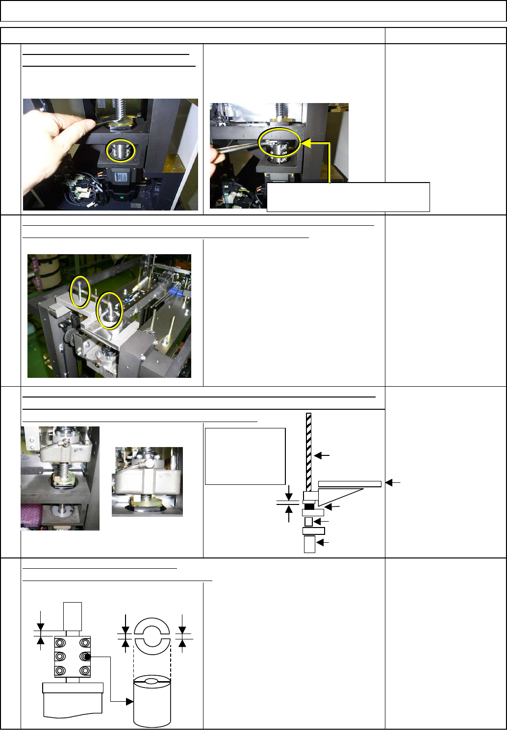
Remove the coupling. Wrench 13mm
return-to-origin process.
hand to hold the gauge as shown in the figure at right.
Tray
11
Item
screw with the other and let the lift descend to the lowest position.
Return the lift-axis to the origin. (See Step 1) Raise the lift with one hand and put
the 10-mm block gauge on the mechanical stopper with the other. Lower the lift by
Hold the lift with one hand, remove the drop-prevention 5-mm Allen key and the
10
Remark
9
The screw should face forward after the
Allen key 4 mm
Wrench 13 and 19 mm
M5 x 6 pcs.
Tighten the lift-axis motor coupling.
Tightening torque: 8.0N•m A=2mm+/-1mm
12
Direct Tray
Block gauge 10 mm
Torque wrench
Allen key 5 mm
Ruler 150 mm
M6 x 6 pcs.
If the cover cannot be removed,
hold here with a 19-mm wrench.
10-mm
Block gauge
Coupling
Motor
Ball screw
Origin: 10-mm
higher than the
mechanical
stopper
Mechanical stopper
A
The amount of the right and the left
gaps should be the same.
Lift
EJM8A-E-SMA070204-A01-00
Page 7-2-4-4