CM602all_EJM8AESM_Service Manual.pdf - 第802页
Remark Component-Thickness-Measuring Unit Option Part and Accessory Replacement Item (1) Insert the light-emitting cable (gray) for the nozzle front line (1 to 6) into the front side of the amplifier connector 40. Next, …
Remark
Component-Thickness-Measuring Unit
Option Part and Accessory Replacement
Item
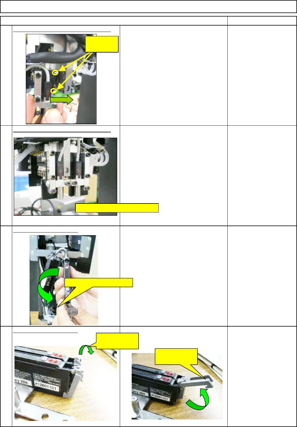
Install the sensor-installin
g
block. -
(
1
)
46
The sensor is positioned with the dowel
pins. Align the hole positions and insert
the sensor straight.
(Light-emitting and -sensing sensors)
* Nozzle arrangements (1 to 6)
⇒ CN40 amplifier
Nozzle arrangements (7 to 12)
⇒ CN30 amplifier
Allen key Long/Short
Install the sensor-installin
g
block. -
(
2
)
Fix the sensor with the M2.5×20L
Hexagonal bolts (2 for each: front and
rear) (The light-emitting sensor is shown
at left. The same applies to the light-
sensing sensor.)
Allen key
* A M3 short wrench is
required.
O
p
en the am
p
lifier cover.
O
p
en the connector lock.
49
48
47
Light-emitting sensor
Open the
connector lock.
Open the
connector lock.
Dowel pins
(2 for each)
M3 Hexagonal bolt (2 for each)
Open the amplifier cover.
EJM8A-E-SMA060402-A01-01
Page 6-4-2-14
Remark
Component-Thickness-Measuring Unit
Option Part and Accessory Replacement
Item
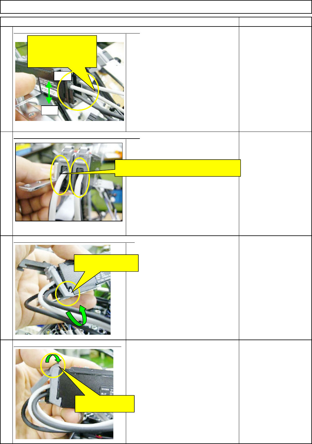
(1) Insert the light-emitting cable (gray) for the
nozzle front line (1 to 6) into the front side of
the amplifier connector 40.
Next, insert the light-sensing cable (black) for
the nozzle front line (1 to 6) into the rear side
of the amplifier connector 40.
(2) Insert the light-emitting cable (gray) for the
nozzle rear line (7 to 12) into the front side of
the amplifier connector 39.
Next, insert the light-sensing cable (black) for
the nozzle rear line (7 to 12) into the rear side
of the amplifier connector 39.
Lock the connector lock of the am
p
lifier.
52
53
50
51
Insert the sensor cables into the amplifier. - (1)
Insert the sensor cables into the amplifier. - (2)
Put the connector-lock hook on the amplifier.
Front
Insert the sensor cables
for the front (1 to 6) and
for the rear (7 to 12) into
the amplifier.
Rear
Put the sensor cables between the connector
locks of the amplifier.
Put the connector-lock
hook on the amplifier.
Lock the connector
lock of the amplifier.
EJM8A-E-SMA060402-A01-01
Page 6-4-2-15
Remark
Component-Thickness-Measuring Unit
Option Part and Accessory Replacement
Item
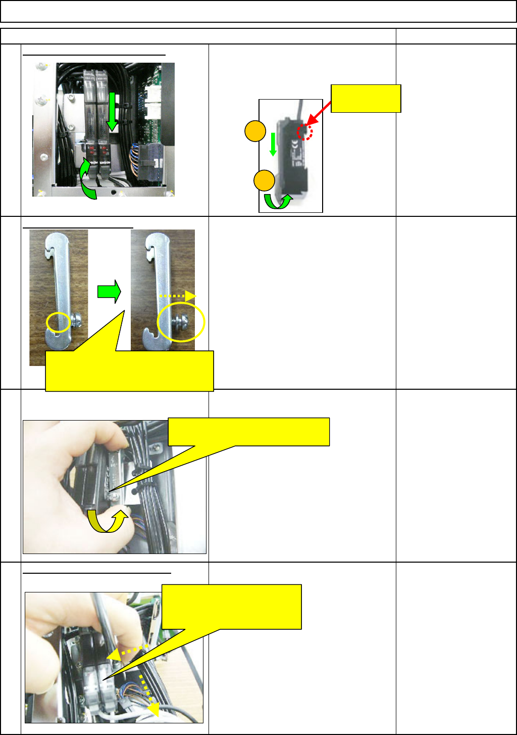
Put the am
p
lifier on the bracket.
54
Move the amplifier in the (1) and (2)
directions below, and fit the amplifier.
Pre
p
are the holdin
g
bolt.
55
Fit the am
p
lifier-holdin
g
bolt. -
(
1
)
56
Fit the am
p
lifier-holdin
g
bolt. -
(
2
)
57
Phillips screwdriver #2
Screw M4
2
1
Press the bolt end of the bracket
against the cables to lock that end.
Pressing the bracket in the
↓ direction and against the
amplifier, tighten the bolt.
This hook can
move.
Loosen the holding bolt until the end
of it does not come out to the
rear side of the bracket.
EJM8A-E-SMA060402-A01-01
Page 6-4-2-16