CM602all_EJM8AESM_Service Manual.pdf - 第471页
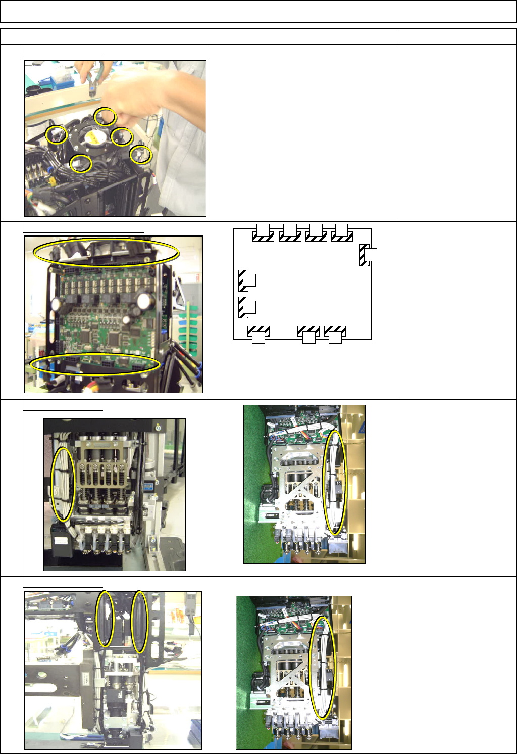
Machinery Part Replacement Remarks Item L ight Transfer-Head Assembly (8-nozzle type ) Remove the front screws. Remove the rear screws. Allen key 3 mm Screw M4x16L 2 pcs. Screw M4x8L 3 pcs. Small round flat washer Transf…
Machinery Part Replacement
Remarks
Item
L
ight Transfer-Head Assembly (8-nozzle type
)
Cut the cable ties.
Nipper
Disconnect the connectors.
Cut the cable ties.
Nipper
Cable tie 100 mm
Cut the cable ties.
Nipper
5
6
7
8
CN1
CN2
CN3 CN4
CN5
CN12
CN10CN9
CN7
CN6
MC14CX
The same boards are installed
at the front and the rear sides
of the head assembly.
EJM8A-E-SMA050314-A01-00
Page 5-3-14-3
Machinery Part Replacement
Remarks
Item
L
ight Transfer-Head Assembly (8-nozzle type
)
Remove the front screws. Remove the rear screws.
Allen key 3 mm
Screw M4x16L 2 pcs.
Screw M4x8L 3 pcs.
Small round flat washer
Transfer head disassembled
When separating the head, check that
the cables do not get caught.
Left: Z-axis controlling board
Right: Z-axis drive unit
TI
g
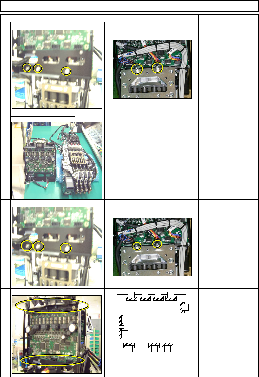
hten the front screws. Ti
g
hten the rear screws.
Allen key 3 mm
Screw M4x16L 2 pcs.
Screw M4x8L 3 pcs.
Small round flat washer
Connect the connectors.
10
11
12
9
CN1
CN2
CN3 CN4
CN5
CN12
CN10CN9
CN7
CN6
MC14CX
The same boards are installed
at the front and the rear sides
of the head assembly.
EJM8A-E-SMA050314-A01-00
Page 5-3-14-4
Machinery Part Replacement
Remarks
Item
L
ight Transfer-Head Assembly (8-nozzle type
)
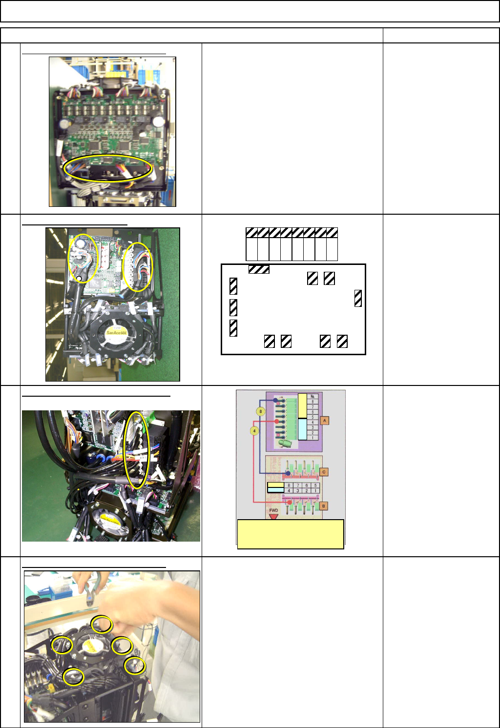
Secure the cables with cable ties.
Nipper
Cable ties
Connect the connectors.
Connect the vacuum release tube.
Magic marker
Air tube 8 pcs.
Secure the cables with cable ties.
Nipper
Cable ties
14)
13
15
16
CN1
CN2
CN3
CN4 CN5 CN6 CN7
CN12
CN8CN9
CN10
MC15CX
8 7 6 5 4 3 2 1
The tubes A, B and C numbers are the
same as part numbers. Connect the
other
tubes referring to the figures above:
R
ear
F
ron
t
Rea
r
Fron
t
EJM8A-E-SMA050314-A01-00
Page 5-3-14-5