CM602all_EJM8AESM_Service Manual.pdf - 第801页
Remark Component-Thickness-Measuring Unit Option Part and Accessory Replacement Item Install the sensor-installin g block. - ( 1 ) 46 The sensor is positioned with the dowel pins. Align the hole positions and insert the …
Remark
Component-Thickness-Measuring Unit
Option Part and Accessory Replacement
Item
Li
g
ht-axis ad
j
ustment -
(
3
)
42
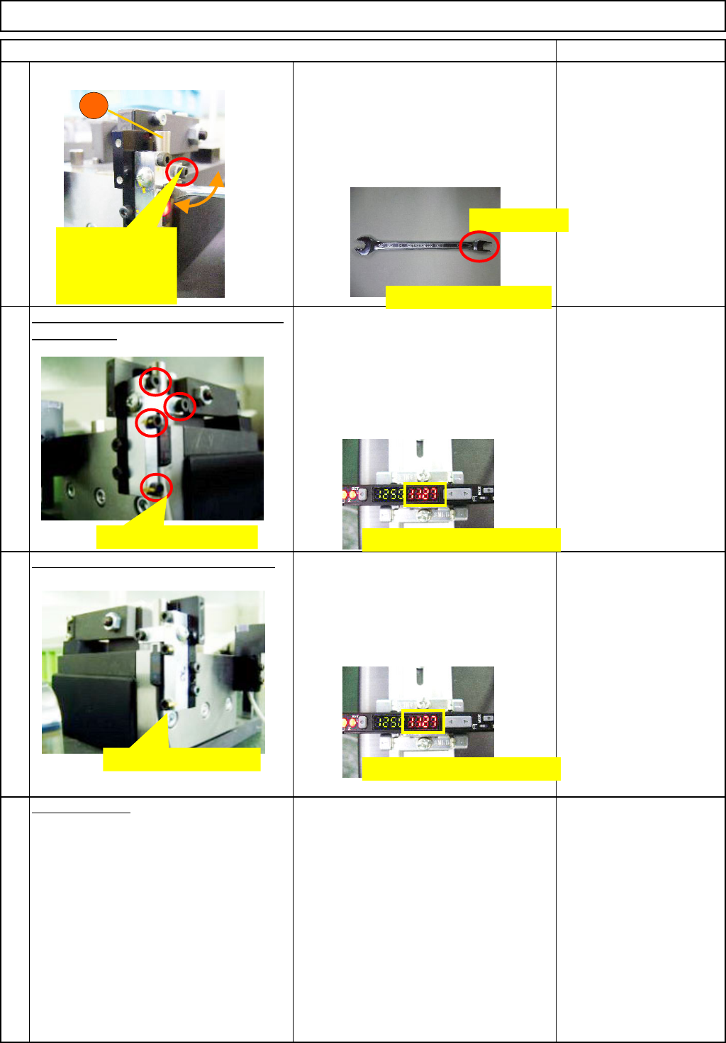
Provisionally fix the sensor (C) loosely
enough to move the sensor by turning it
with a special wrench. Moving the
sensor in the arrow direction, find a point
at which the amplifier level reaches
maximum and provisionally fix the
sensor.
Special wrench (size 6)
Allen key Long/Short
Securel
y
ti
g
hten the blocks A and B and
43
the sensor C.
Repeat "Light-axis adjustment (1), (2) or
(3)" until the amplifier level reaches 1000
or more. Securely tighten the blocks A
and B, and the sensor C. After securely
tightening them, check the amplifier level
is 1000 or more.
Allen key Long/Short
Securel
y
ti
g
hten the li
g
ht-sensin
g
side.
44
Securely tighten the four light-sensing-
sensor bolts. Check the amplifier level is
1000 or more.
Allen key Long/Short
Remove the
j
i
g
.
45
1. Switch off the jig. Remove the sensor
connector.
2. Remove the sensor block from the
light-axis-adjusting jig.
C
Provisionally
fix it loosely
enough to move
it with a wrench.
Special wrench (size 6)
H-shaped cut
Securely tighten them.
Securely tighten them
Amplifier level 1000 or more
Amplifier level 1000 or more
EJM8A-E-SMA060402-A01-01
Page 6-4-2-13
Remark
Component-Thickness-Measuring Unit
Option Part and Accessory Replacement
Item
Install the sensor-installin
g
block. -
(
1
)
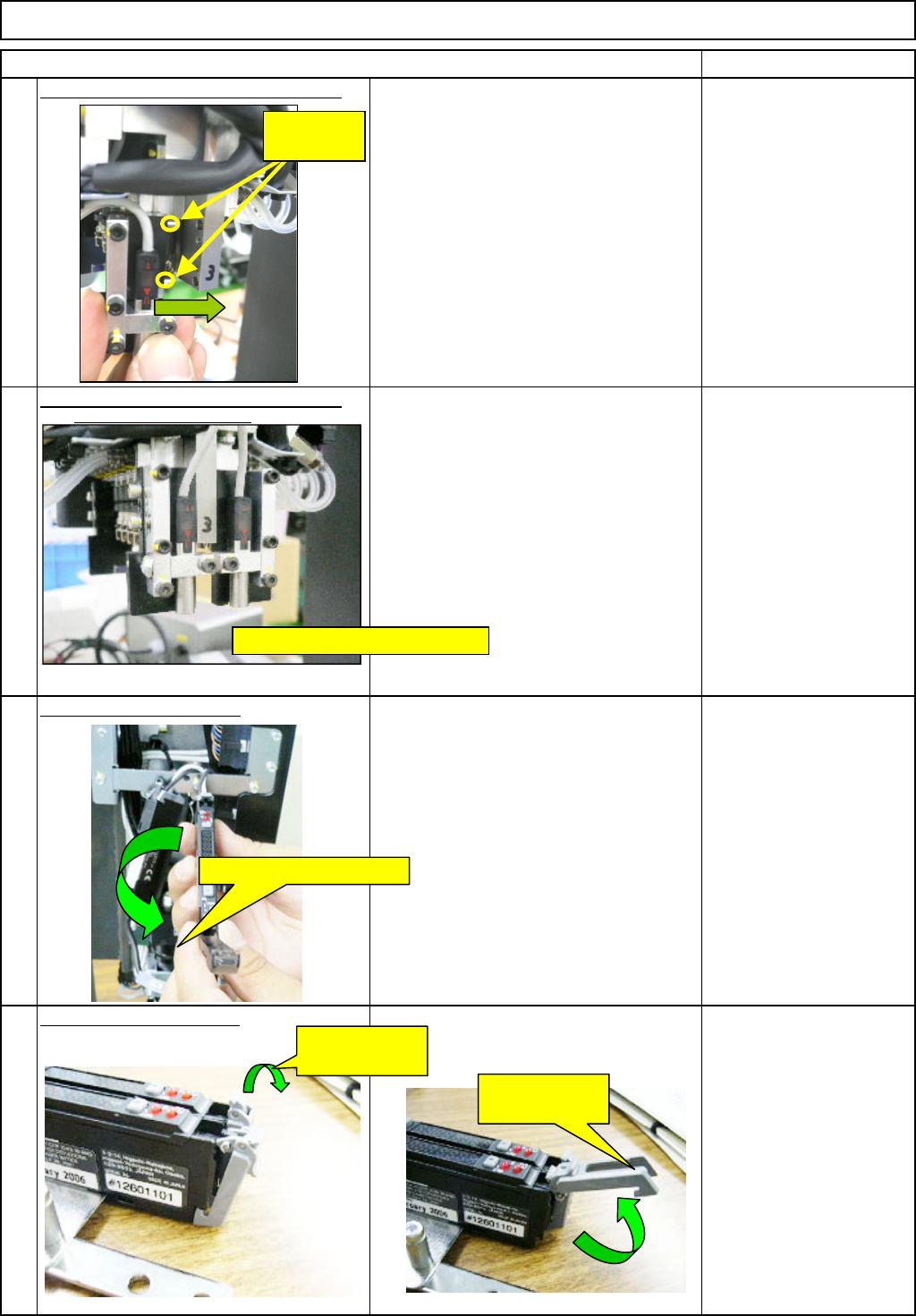
46
The sensor is positioned with the dowel
pins. Align the hole positions and insert
the sensor straight.
(Light-emitting and -sensing sensors)
* Nozzle arrangements (1 to 6)
⇒ CN40 amplifier
Nozzle arrangements (7 to 12)
⇒ CN30 amplifier
Allen key Long/Short
Install the sensor-installin
g
block. -
(
2
)
Fix the sensor with the M2.5×20L
Hexagonal bolts (2 for each: front and
rear) (The light-emitting sensor is shown
at left. The same applies to the light-
sensing sensor.)
Allen key
* A M3 short wrench is
required.
O
p
en the am
p
lifier cover.
O
p
en the connector lock.
49
48
47
Light-emitting sensor
Open the
connector lock.
Open the
connector lock.
Dowel pins
(2 for each)
M3 Hexagonal bolt (2 for each)
Open the amplifier cover.
EJM8A-E-SMA060402-A01-01
Page 6-4-2-14
Remark
Component-Thickness-Measuring Unit
Option Part and Accessory Replacement
Item
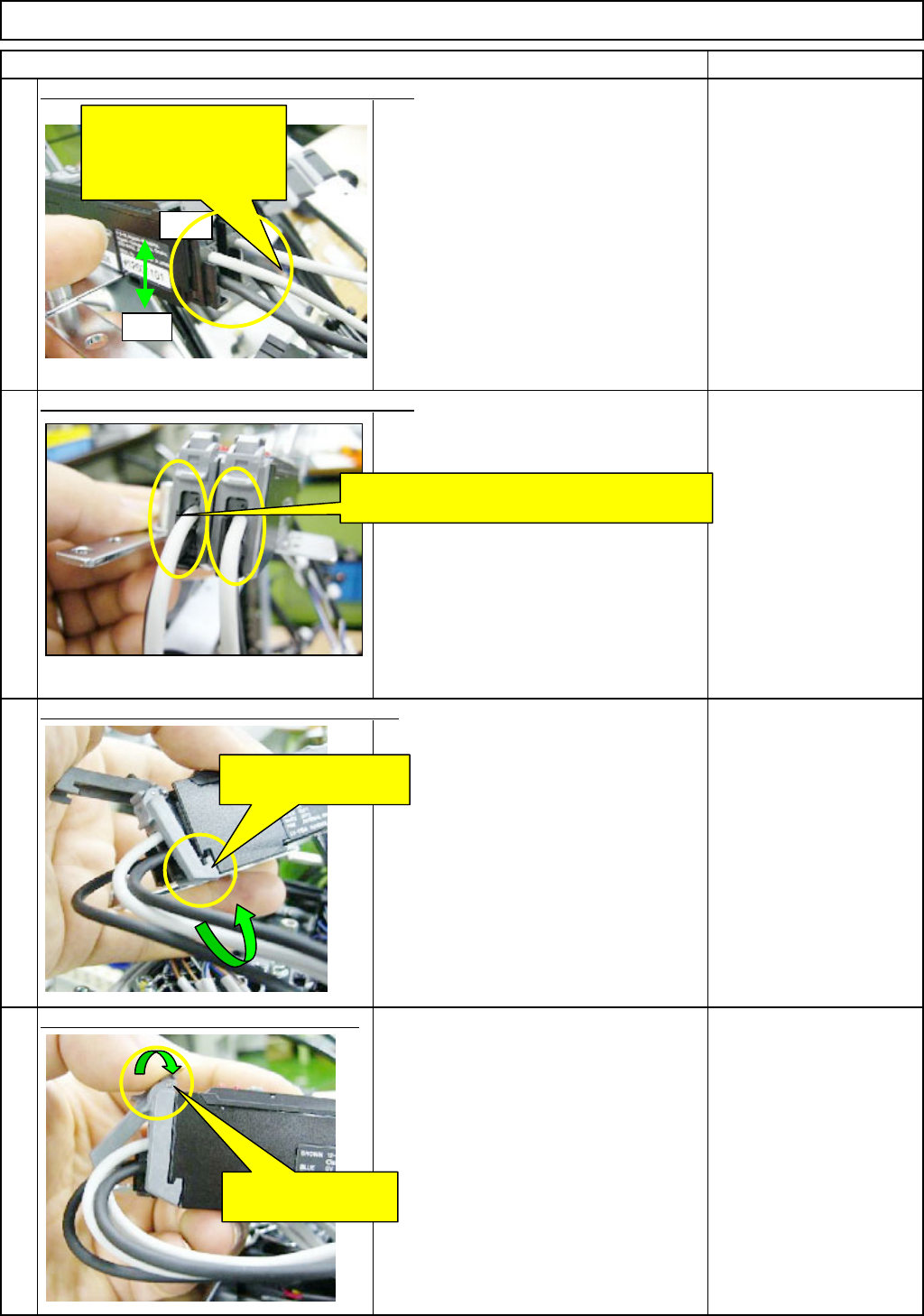
(1) Insert the light-emitting cable (gray) for the
nozzle front line (1 to 6) into the front side of
the amplifier connector 40.
Next, insert the light-sensing cable (black) for
the nozzle front line (1 to 6) into the rear side
of the amplifier connector 40.
(2) Insert the light-emitting cable (gray) for the
nozzle rear line (7 to 12) into the front side of
the amplifier connector 39.
Next, insert the light-sensing cable (black) for
the nozzle rear line (7 to 12) into the rear side
of the amplifier connector 39.
Lock the connector lock of the am
p
lifier.
52
53
50
51
Insert the sensor cables into the amplifier. - (1)
Insert the sensor cables into the amplifier. - (2)
Put the connector-lock hook on the amplifier.
Front
Insert the sensor cables
for the front (1 to 6) and
for the rear (7 to 12) into
the amplifier.
Rear
Put the sensor cables between the connector
locks of the amplifier.
Put the connector-lock
hook on the amplifier.
Lock the connector
lock of the amplifier.
EJM8A-E-SMA060402-A01-01
Page 6-4-2-15