CM602all_EJM8AESM_Service Manual.pdf - 第287页
Td4Z4C-a-SHA : Type A High-speed head shadow teaching Td4Z4C-a-DIR : Type A High-speed head direct teaching Td4Z4C-b-45D : Type B Multi-purpose head 45°teaching Td4Z4C-b-90D : Type B Multi-purpose head 90°teaching Td4Z4C…
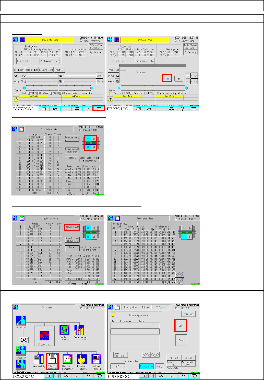
Press AR (BR) button so that:
AF(BF) is selected.
AR(BR) is NOT selected.
Press AF(BF) button so that
AF(BF) is NOT selected.
E327014C AR(BR) is selected.
To display the average of front and rear,
select both front and rear.
Cpk target
602 precision data: Cpk=1.800 or more
(If average is 0.005 or more, it is necessary to correct.)
If accuracy is not achieved for each tray separately, see Step 37.
E327013C
E327014C
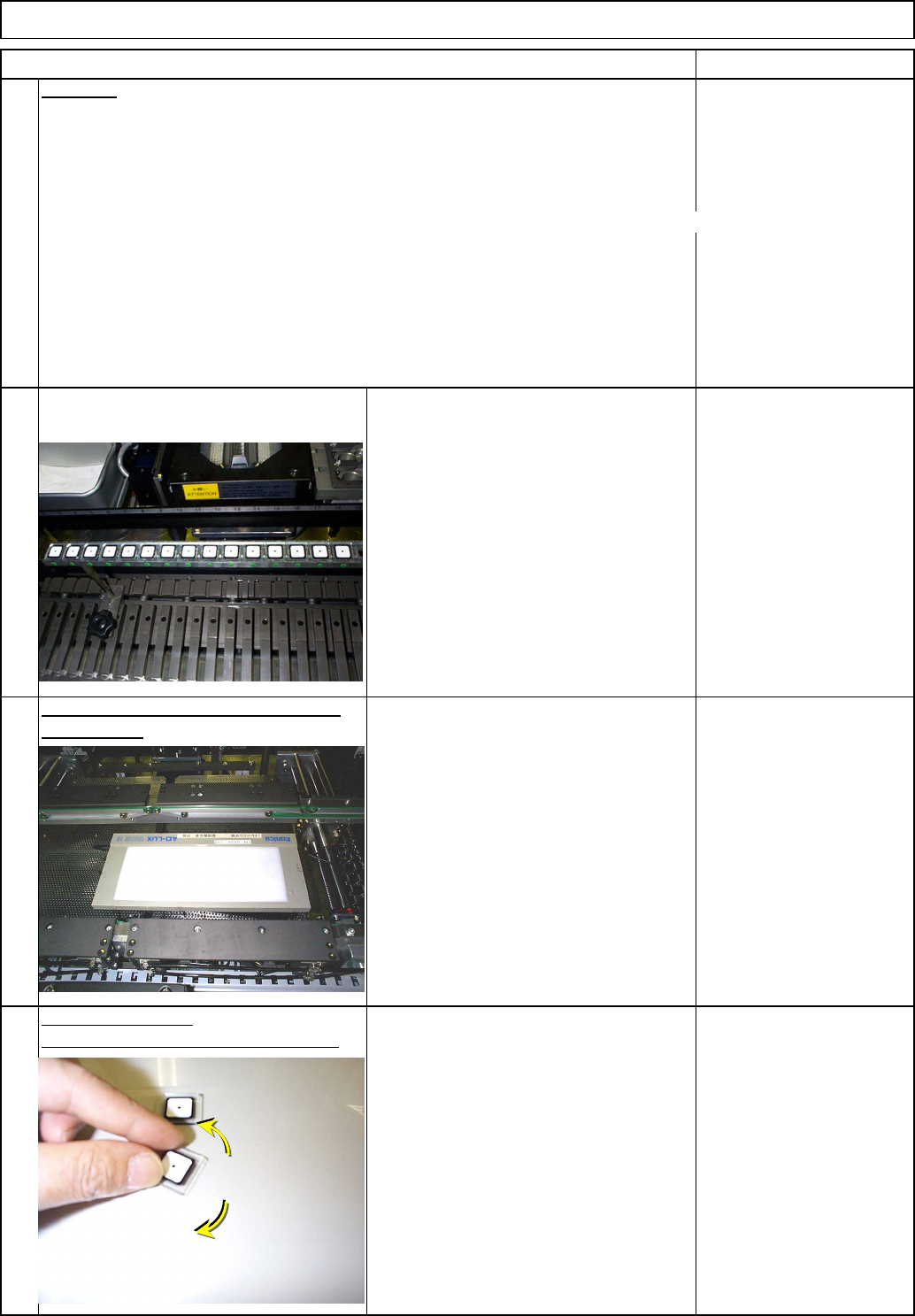
Check how much one component is shifted. (Check only)
Light Transfer-Head Assembly(3 nozzles)
Check the accuracy verifying data placed
30
31
in the machine parameters.
Maintenance Adjustment
29
After the machine stops, press the
Press [Yes].
ITEM REMARKS
"Return" key.
32
Load data. (90°teaching)
EJM8A-E-SMA040307-A01-00
Page 4-3-7-10
Td4Z4C-a-SHA : Type A High-speed head shadow teaching
Td4Z4C-a-DIR : Type A High-speed head direct teaching
Td4Z4C-b-45D : Type B Multi-purpose head 45°teaching
Td4Z4C-b-90D : Type B Multi-purpose head 90°teaching
Td4Z4C-c-S45
: Type C High-speed shadow teaching, Multi-purpose head 45°teaching
Td4Z4C-c-D90
: Type C High-speed direct teaching, Multi-purpose head 90°teaching
* Type C: High-speed head at Stage A, Multi-purpose head at Stage B
Follow Steps 11 to 33.
Remove the QFP jigs, rotating them to
avoid breaking the jigs.
Light Transfer-Head Assembly(3 nozzles)
REMARKS
34
Data type
Maintenance Adjustment
ITEM
33
35
the light box.
36
Remove the QFP jigs from the board.
Place the jigs again.
Once the teaching is finished, remove
Remove the board.
EJM8A-E-SMA040307-A01-00
Page 4-3-7-11
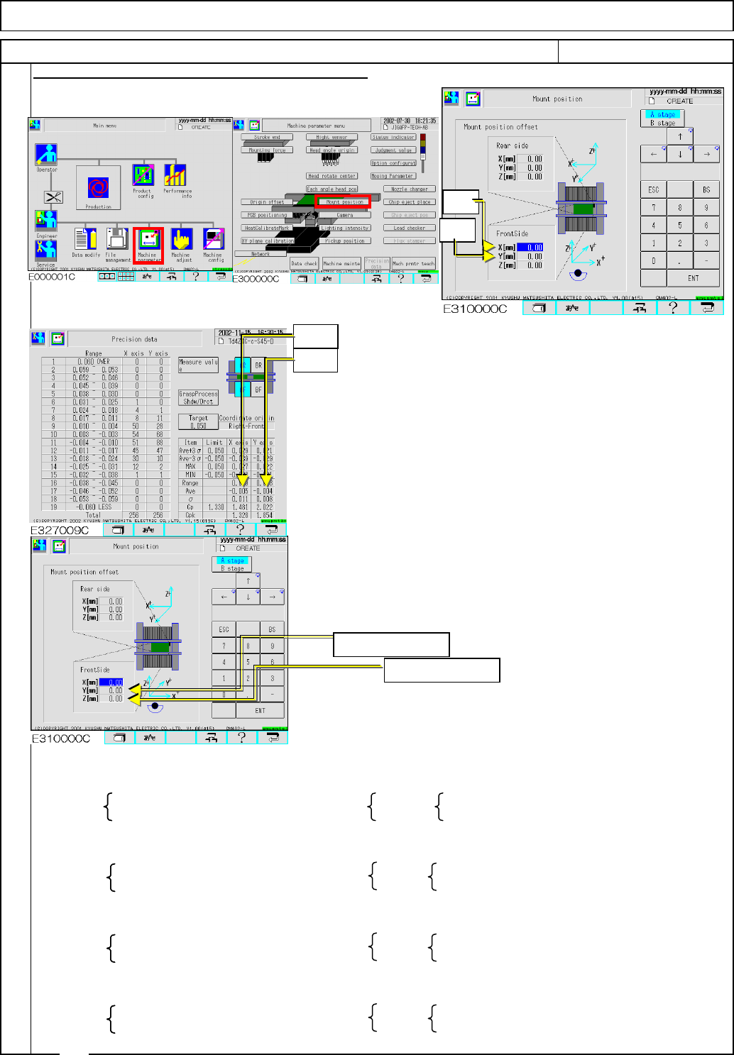
If there is a table whose average is 0.005 or more
correct the mounting position following the procedures below:
Precision data offset
Average of X-axis values……Xave
Average of Y-axis values……Yave
Mounting position offset
X(mm) value ……… Xos
Y(mm) value ………Yos
From the preset mounting position offset ([Preset Xos]
[Preset Yos]) and the average of precision data ([Xave, Yave]),
mounting position offsets to be set ([New Xos][New Yos]) are
calculated as follows:
Enter the mounting position offset ([New Xos][New Yos]).
Then follow Steps 25 to 31and check the precision data.
Right front reference
[New Xos]=[Preset Xos]+Xave [New Xos]=[Preset Xos]-Xave
[New Yos]=[Preset Yos]-Yave [New Yos]=[Preset Yos]+Yave
Left front reference
[New Xos]=[Preset Xos]-Xave [New Xos]=[Preset Xos]+Xave
[New Yos]=[Preset Yos]-Yave [New Yos]=[Preset Yos]+Yave
Right inner-side reference
[New Xos]=[Preset Xos]+Xave [New Xos]=[Preset Xos]-Xave
[New Yos]=[Preset Yos]+Yave [New Yos]=[Preset Yos]-Yave
Left inner-side reference
[New Xos]=[Preset Xos]-Xave [New Xos]=[Preset Xos]+Xave
[New Yos]=[Preset Yos]+Yave [New Yos]=[Preset Yos]-Yave
Procedures for Entering the Mounting Position Offset
Front Rear
Front Rear
37
Rear
Front Rear
Light Transfer-Head Assembly(3 nozzles)
Front
Maintenance Adjustment
ITEM REMARKS
Xave
Yave
Xos
Yos
Enter new Xos.
Enter new Yos.
EJM8A-E-SMA040307-A01-00
Page 4-3-7-12