CM602all_EJM8AESM_Service Manual.pdf - 第933页
Measure the distance from the dog to the mechanical stopper. Install the motor shaft holder. Tension the belt. Item Remarks 13 Allen key 3 mm Allen key 4mm Screw M4 2 pcs. Screw M5 2 pcs. Switch on the power. Fit the jig…
Item Remarks
Tray
Secure the cables with a cable tie.
9
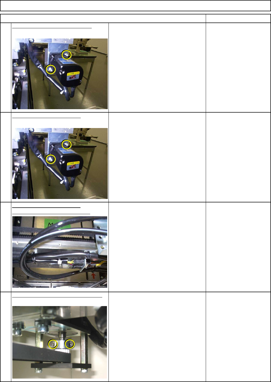
Remove the motor holding screws.
Allen key 4 mm
Screw M5 2 pcs.
Allen key 4 mm
Screw M5 2 pcs.
Replace and install the motor.
Connect the motor connector.
10
11
12
Shuttle Tray
Allen key 1.5 mm
Setscrew M3
Nipper
Tighten the motor shaft holding screws.
EJM8A-E-SMA070109-A01-00
Page 7-1-9-4
Measure the distance from the dog to the mechanical stopper.
Install the motor shaft holder.
Tension the belt.
Item Remarks
13
Allen key 3 mm
Allen key 4mm
Screw M4 2 pcs.
Screw M5 2 pcs.
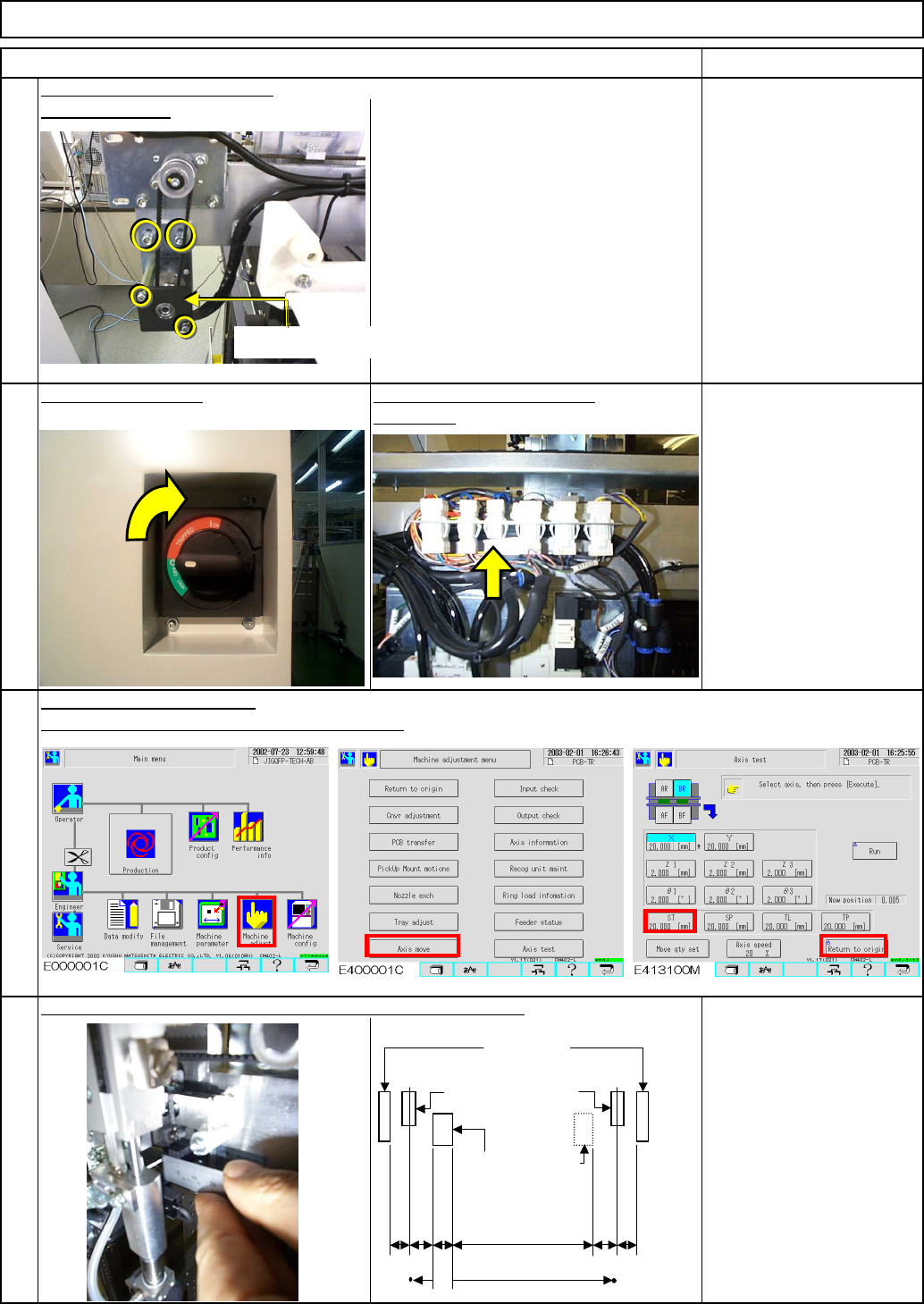
Switch on the power.
Fit the jig on the door switch
connector.
15
Carry out "Return to origin."
(Be sure to keep yourself off the drive section.)
16
Distance from Dog to
Stopper:
9.5 mm ±1 mm
14
Tray Shuttle Tray
Motor axis holder
3
6.5 36.5
(30)
4.5
731.5
727st
-O/R
StrokeOrigin
+O/R
Mechanical
stopper
Dog
+soft limit -soft limit
EJM8A-E-SMA070109-A01-00
Page 7-1-9-5
Adjustable distance: +/- 3 mm
(The hole is 3-mm long.)
12
34
Remove the jig from the door
Item Remarks
Shuttle TrayTray
17
Allen key 3 mm
Screw M4 2 pcs.
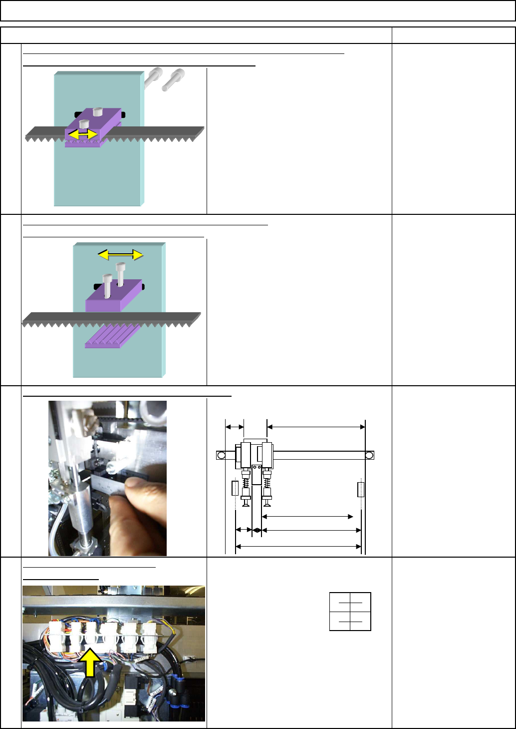
If it is necessary to adjust the distance, loosen the bolts that are positioned
at the back of the belt clamp, and adjust the distance.
18
Allen key 3 mm
Screw M4 2 pcs.
If it is necessary to adjust the distance more than 3 mm,
loosen the bolts below and move the belt.
19
Carry out "Return to origin." Check the distance.
20
switch connector.
30
B
A=727st
(770)
C
D
E
EJM8A-E-SMA070109-A01-00
Page 7-1-9-6