CM602all_EJM8AESM_Service Manual.pdf - 第545页
Refer to "Replacing a Set of Head Units." 18 Install a set of head units. Tools and Specifications Section 5-5-1 17 Connect the connectors. Tools and Specifications Item Remarks Machinery Part Replacement Z Uni…
Refer to "Head Unit Replacement."
16
Put the upper board bracket back on.
Tools and Specifications
Allen key 3 mm
Allen key 4 mm
Screw M4x8L 1 pc.
M5x12L 3 pcs.
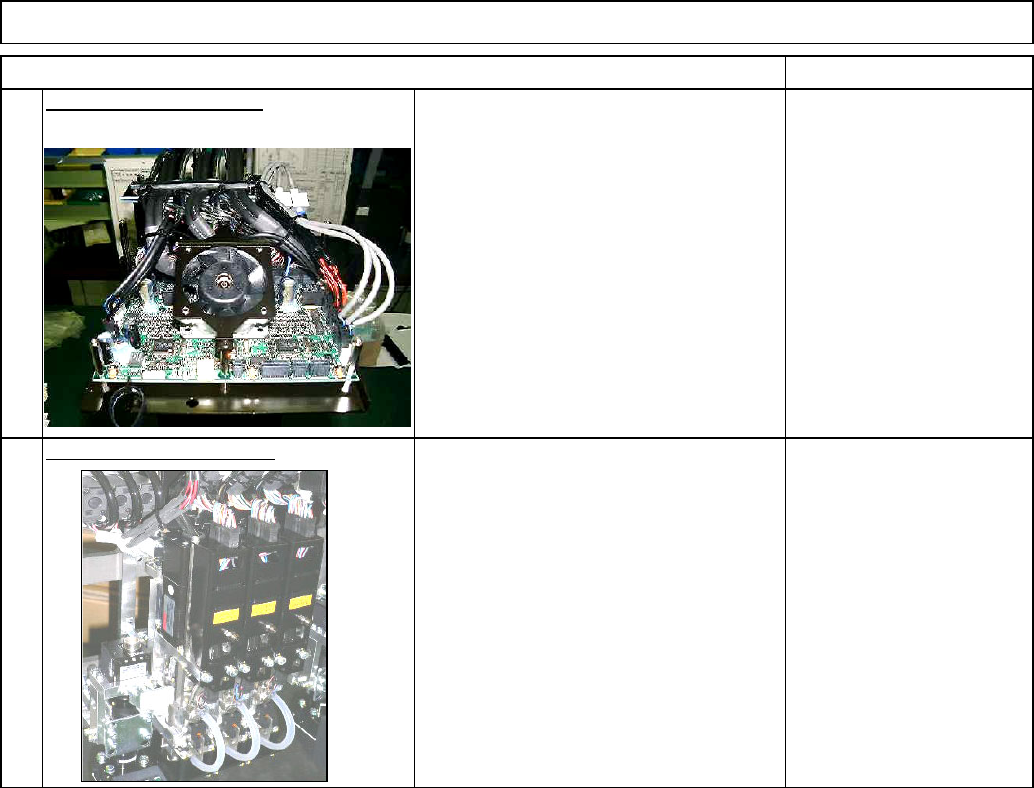
15
Put the head unit back on.
Tools and Specifications
Section 5-4-2
Allen key 2.5 mm
Screw M3x8L 4 pcs.
14
Tools and Specifications
Install the Z-axis motor. Remarks
13
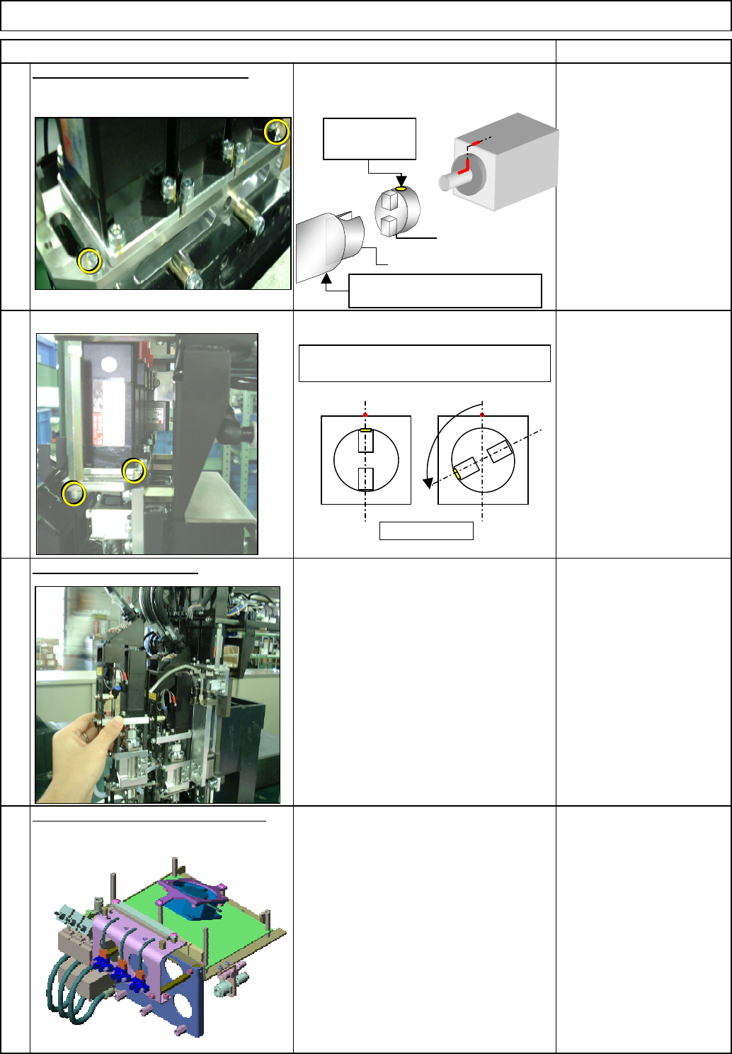
Place the Z-axis motor in position.
Tools and Specifications
Allen key 2.5 mm
Screw M4 x 5L 2 pcs.
Machinery Part Replacement
Z Unit (3-nozzle type)
Raise the linear guide to
maximum.
D
E
Top view
The screw hole of "D" should be positioned
more than 90 degrees away from the
k
Screw-hole
position
EJM8A-E-SMA050509-A01-00
Page 5-5-9-5
Refer to "Replacing a Set of Head Units."
18
Install a set of head units.
Tools and Specifications
Section 5-5-1
17
Connect the connectors.
Tools and Specifications
Item Remarks
Machinery Part Replacement
Z Unit (3-nozzle type)
EJM8A-E-SMA050509-A01-00
Page 5-5-9-6
Machinery Part Replacement
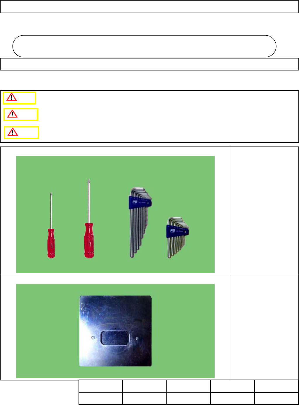
・Tools
Phillips screwdriver #1
Phillips screwdriver #2
Allen key 3 mm
・Jig
FM-1112
Head Camera Height
Adjusting Jig
Head Camera Unit
5-6-1 Head Camera and LED Replacement
This section describes the procedures for replacing the head camera and the LED.
Caution
Dange
r
Warning
Head Camera Uni
t
5-6
Assembly
Adjustment
42min.
Teaching
min.
Total Time Weight of
Part
Removal
Disassembly
20min.
62min.
kgs
EJM8A-E-SMA050601-A01-00
Page 5-6-1-1