CM602all_EJM8AESM_Service Manual.pdf - 第655页
Machinery Part Replacement Remark 12-Nozzle Head Unit Item Turn on the power and air supply. カバー達 A d j ustment Teaching Head Camera Adjustment (Focus and θ) Board Recognition Camera XY Origin Offset Z-axis Origin Offse…
Machinery Part Replacement
Remark
12-Nozzle Head Unit
Item
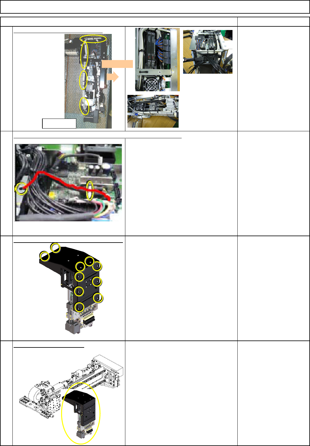
Secure the cable with a cable tie.
Nipper
Cable tie
Insert the
θ motor connector. Secure the cable with a cable tie.
Nipper
Cable tie
Put the front and the top covers back on.
Phillips screwdriver #2
M4 truss screw 10 pcs.
Put the head unit back on.
1-000279
See "12-Nozzle-Head-Unit
Replacement."
Section 5-10-1
24
25
23
26
<Left side>
Front
EJM8A-E-SMA051008-A01-00
Page 5-10-8-8
Machinery Part Replacement
Remark
12-Nozzle Head Unit
Item
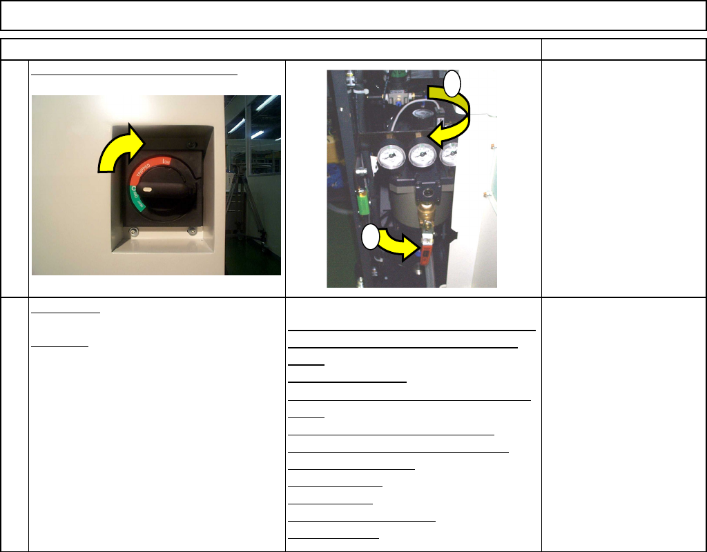
Turn on the power and air supply.
カバー達
A
d
j
ustment
Teaching
Head Camera Adjustment (Focus and θ)
Board Recognition Camera XY Origin
Offset
Z-axis Origin Offset
Chip Recognition Camera, θ-axis Origin
Offset
Width Adjusting-axis Origin Offset
Mount Height and Board Positioning
XY Plane Calibration
Pickup Position
Light Intensity
Nozzle Change Position
Mount Position
Section 5-11-1
Section 5-11-2
Section 5-11-3
Section .5-11-4
Section 5-11-5
Section 5-11-6
Section 5-11-7
Section 5-11-8
Section 5-11-9
Section 5-11-10
Section 5-11-11
27
28
1
2
EJM8A-E-SMA051008-A01-00
Page 5-10-8-9
Machinery Part Replacement
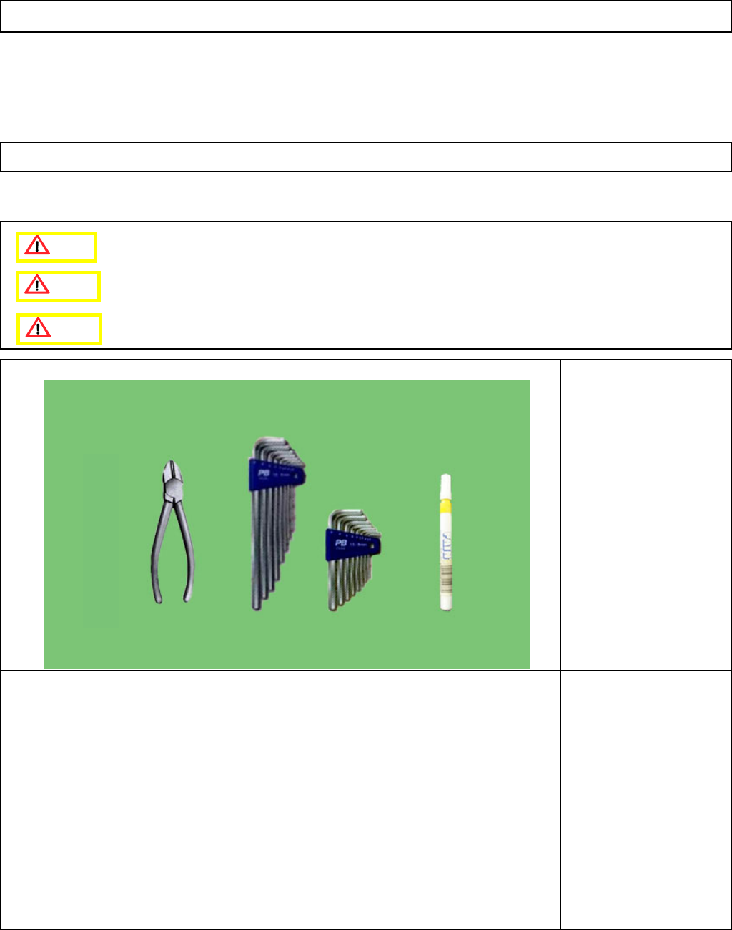
This section describes the procedures for removing the upper frame and the Z-axis unit.
Tools
Allen key 3 mm
Nipper
Magic marker
Jig
None
12-Nozzle Head Unit
5-10-9 Removing the Upper Frame and the Z-axis Unit
Caution
Dange
r
Warning
EJM8A-E-SMA051009-A01-00
Page 5-10-9-1