CM602all_EJM8AESM_Service Manual.pdf - 第794页
Remark Component-Thickness-Measuring Unit Option Part and Accessory Replacement Item Remove the sensor-mountin g block. - ( 1 ) Loosen the "M2.5 x 20L" hexagonal bolts (2 for each: front and rear). Remove the b…
Remark
Component-Thickness-Measuring Unit
Option Part and Accessory Replacement
Item
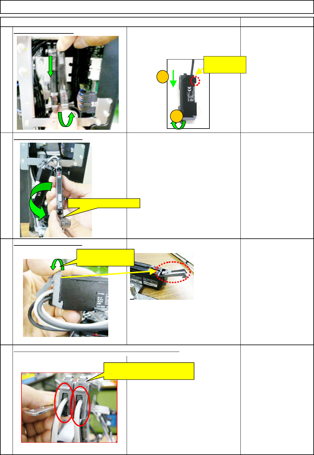
Remove the am
p
lifier.
Move the amplifier in the (1) and (2)
directions below, and remove the
amplifier.
O
p
en the am
p
lifier cover.
17
Open the connector lock.
19
16
18
Remove the sensor cables from the amplifier-connector lock.
Open the connector
lock.
Remove the sensor cables from
the amplifier-connector locks.
Open the amplifier cover.
1
2
This hook can
move.
EJM8A-E-SMA060402-A01-01
Page 6-4-2-6
Remark
Component-Thickness-Measuring Unit
Option Part and Accessory Replacement
Item
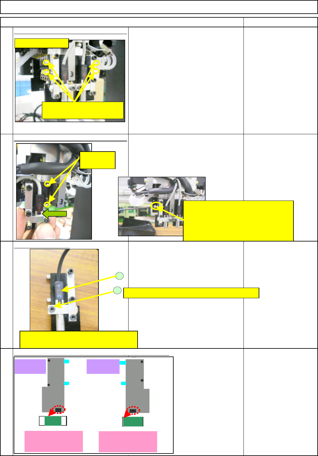
Remove the sensor-mountin
g
block. -
(
1
)
Loosen the "M2.5 x 20L" hexagonal bolts
(2 for each: front and rear).
Remove the bolts.
(The left picture shows the light-emitting
side. The same applies to the light-
sensing side.)
Allen key
* A M2.5 short wrench is
required.
Remove the sensor-mountin
g
block. -
(
2
)
The block is positioned with the dowel
pins. Pull the block towards you straight
and remove it. (The same to both sides:
light-emitting and -sensing sides)
Remove the sensor.
Loosen (2) and remove the sensor (1).
<Caution>
A light-emitting side and a light-sensing
side should be replaced as a set.
(because there is one connector.)
20
21
22
23
How to distinguish the light-emitting and -sensing plates:
M2.5 x 20L
(Two for each: right and left)
2
1
The light-sensing sensor is shown above.
Sensor: LV-S7250(2734)
M2.5x8L Small flat and round washer M2.5
Light-emitting side
Plate (A)Plate (B)
When the block cannot be removed:
There is a pressing-screw hole in the
center of the two block-mounting-bolt
holes. Screw the removed bolt into this
hole and pull the block out straight.
Dowel pins
(2 for each)
Light-sensing side:
Light-blocked black
area of
g
lass: Small
Light-emitting side
Light-blocked black
area of
g
lass: Lar
g
e
EJM8A-E-SMA060402-A01-01
Page 6-4-2-7
Remark
Component-Thickness-Measuring Unit
Option Part and Accessory Replacement
Item
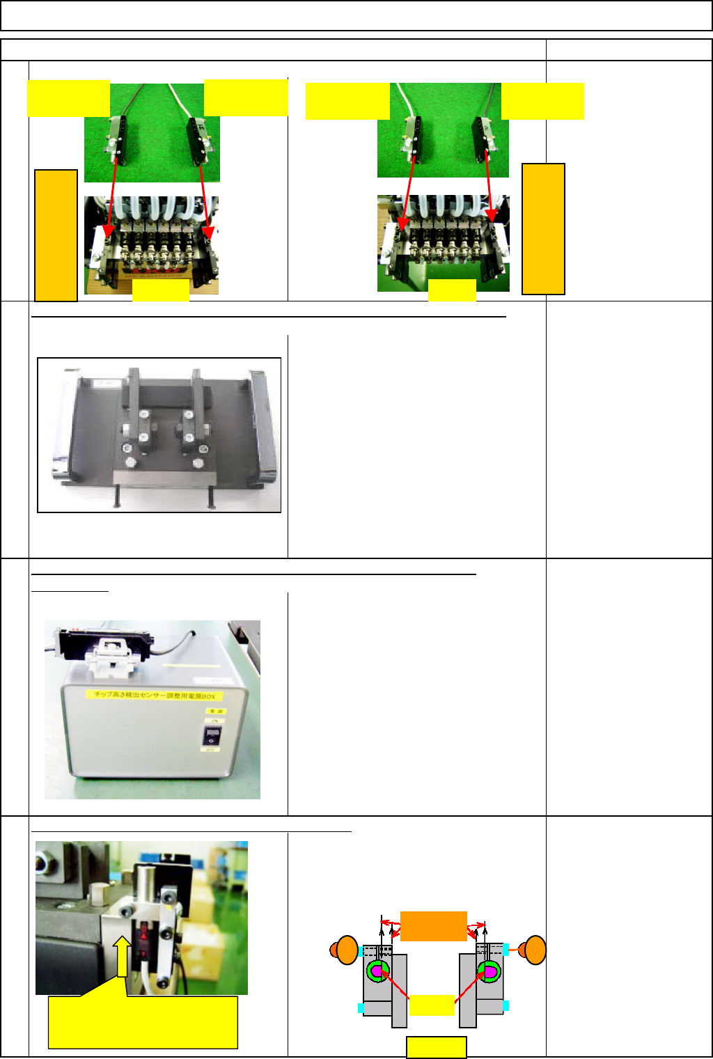
24
FM-1853(2)
Component-thickness-
sensor-light-axis-
adjusting jig
FM-1853(1)
Component-height-
detection-sensor-
adjusting power source
27
Position the D-shaped cut of each sensor
(light-emitting and -sensing) as shown in the
Figure 1 below. Insert each sensor from the
bottom up to the step and provisionally fix it
with the "M2.5×8L" bolt (1) or (2).
Prepare the component-height-detection-sensor-adjusting power source
FM-1853
(
1
)
.
Provisionally mount the new sensor. (front and rear)
25
26
Position the sensors correctly as shown below when installing them.
Prepare the component-thickness-sensor-light-axis-adjusting jig FM-1853(2).
Light-sensing
(Black cable)
Light-emitting
(Gray cable)
Left
(
Head-camera side
)
FRONT REAR
Insert the sensor from the bottom
up to the step. (The same to light-
emitting and -sensing sides)
Light-emitting
(Gray cable)
Light-sensing
(Black cable)
Right
(
Head-camera side
)
Figure 1
1 2
Should be
parallel
D-shaped
cu
t
EJM8A-E-SMA060402-A01-01
Page 6-4-2-8