CM602all_EJM8AESM_Service Manual.pdf - 第654页
Machinery Part Replacement Remark 12-Nozzle Head Unit Item Secure the cable with a cable tie. Nipper Cable tie Insert the θ motor connector. Secure the cable with a cable tie. Nipper Cable tie Put the front and the top c…
Machinery Part Replacement
Remark
12-Nozzle Head Unit
Item
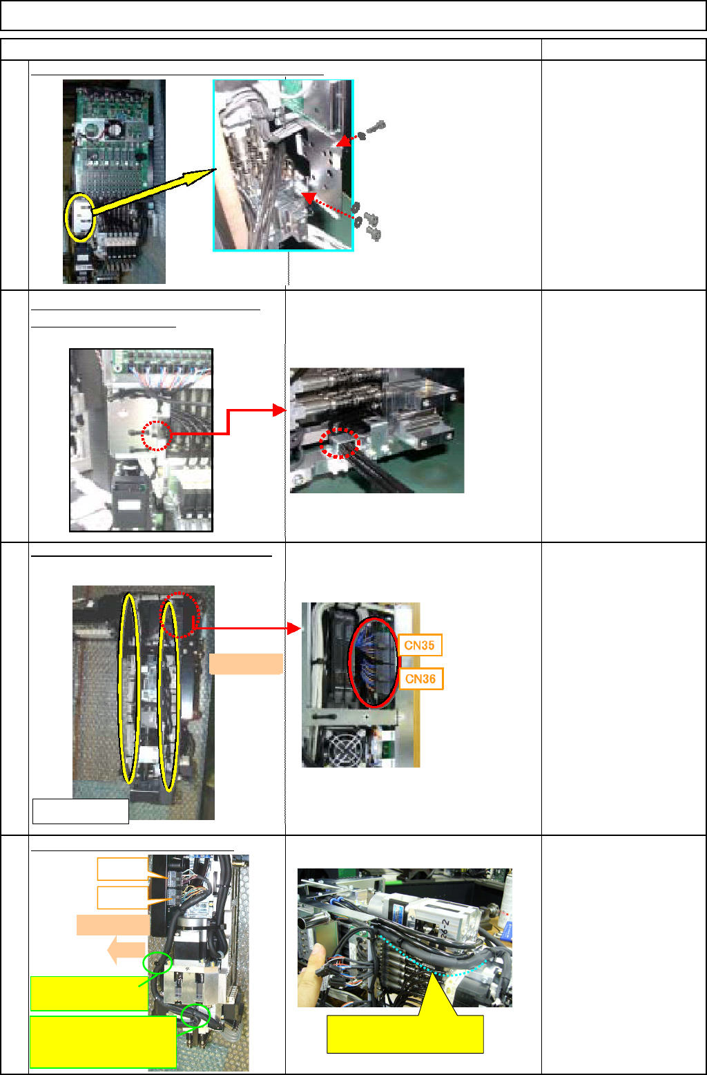
Put the cable and tube holding bracket back on.
Allen key
M3 x 6L 3 pcs.
Put the tube-holding bracket back on.
Insert the vacuum tube.
20
Connect the vacuum sensor connector.
Secure the cable with a cable tie.
Nipper
Cable tie
Secure the cable with a cable tie.
21
22
19
CN31
CN32
Front
II: Cable-tie
holde
r
The cable should not
curved widely.
Front
<Left side>
I: Cable-tie holder
(Wiring of VL1 to 6
and VL7 to 12
)
EJM8A-E-SMA051008-A01-00
Page 5-10-8-7
Machinery Part Replacement
Remark
12-Nozzle Head Unit
Item
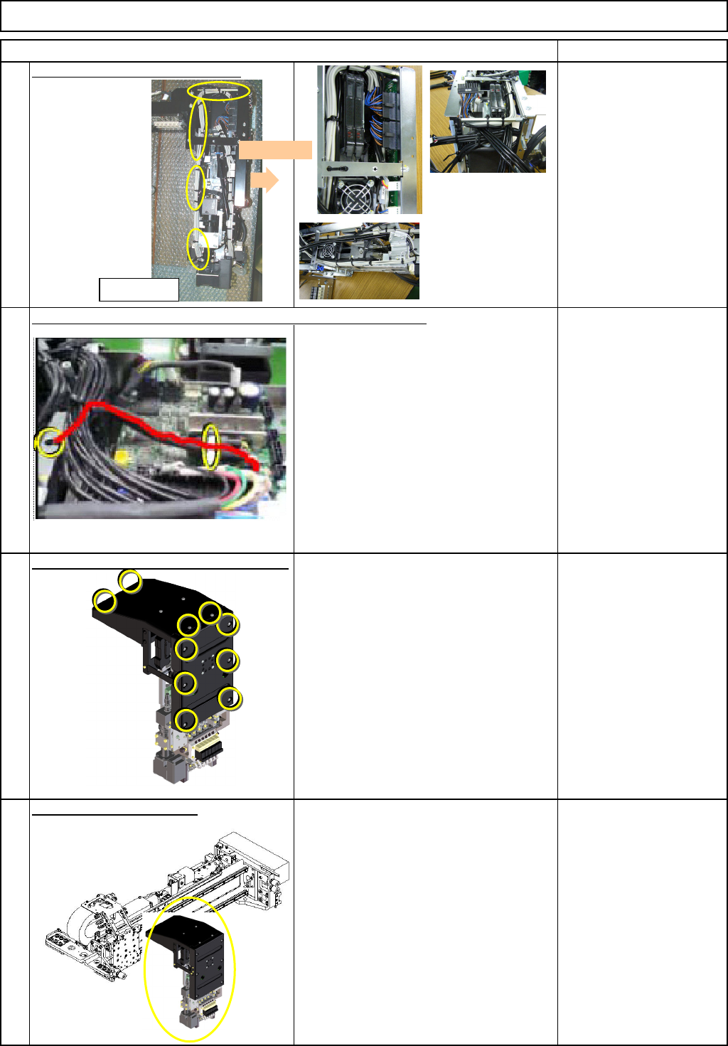
Secure the cable with a cable tie.
Nipper
Cable tie
Insert the
θ motor connector. Secure the cable with a cable tie.
Nipper
Cable tie
Put the front and the top covers back on.
Phillips screwdriver #2
M4 truss screw 10 pcs.
Put the head unit back on.
1-000279
See "12-Nozzle-Head-Unit
Replacement."
Section 5-10-1
24
25
23
26
<Left side>
Front
EJM8A-E-SMA051008-A01-00
Page 5-10-8-8
Machinery Part Replacement
Remark
12-Nozzle Head Unit
Item
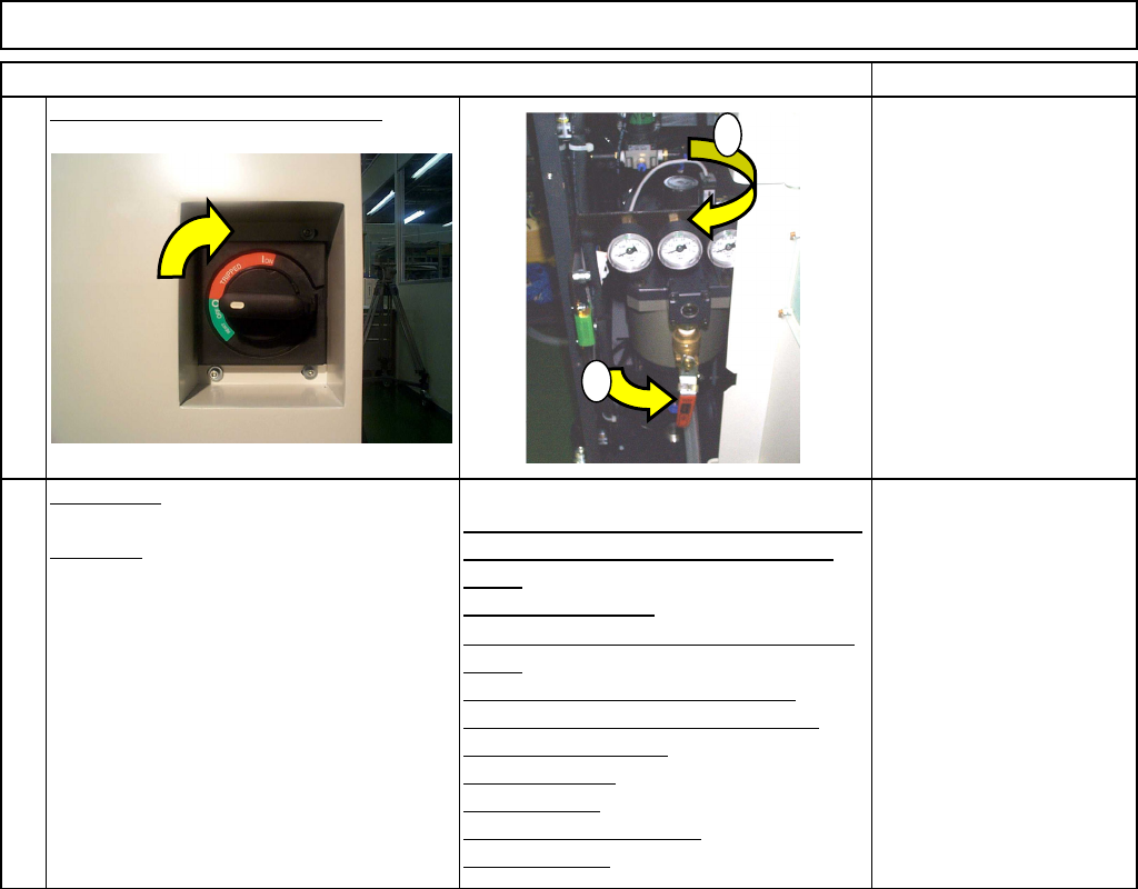
Turn on the power and air supply.
カバー達
A
d
j
ustment
Teaching
Head Camera Adjustment (Focus and θ)
Board Recognition Camera XY Origin
Offset
Z-axis Origin Offset
Chip Recognition Camera, θ-axis Origin
Offset
Width Adjusting-axis Origin Offset
Mount Height and Board Positioning
XY Plane Calibration
Pickup Position
Light Intensity
Nozzle Change Position
Mount Position
Section 5-11-1
Section 5-11-2
Section 5-11-3
Section .5-11-4
Section 5-11-5
Section 5-11-6
Section 5-11-7
Section 5-11-8
Section 5-11-9
Section 5-11-10
Section 5-11-11
27
28
1
2
EJM8A-E-SMA051008-A01-00
Page 5-10-8-9