CM602all_EJM8AESM_Service Manual.pdf - 第408页
Machinery Part Replacement Remarks Item Transfer Head Assembly (8-nozzle type) Connect the air tube. Connect the connectors. Secure the earth cable with a cable tie. Phillips screwdriver #2 Round cross-head screw M4 1 pc…
Machinery Part Replacement
Remarks
Item
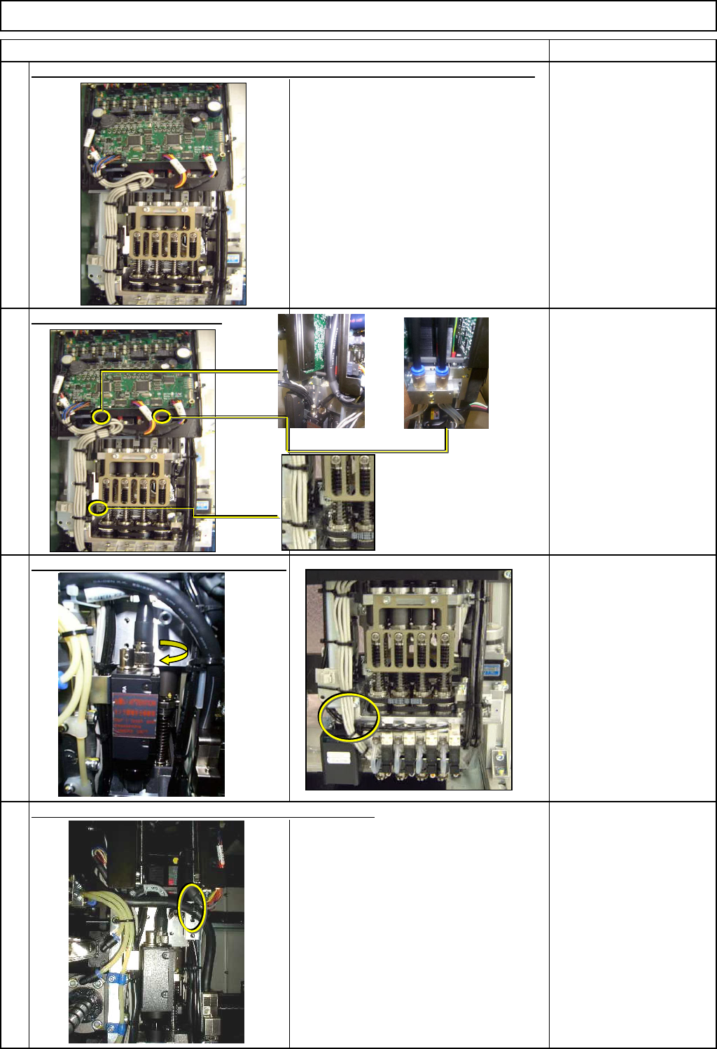
Transfer Head Assembly (8-nozzle type)
Head installing dowel pin
Tighten the head holding bolts.
Allen key 5 mm
Pipe
Screw M6 x 3
Connect the camera and the LED cables.
Connector
Cable tie 150 x1
Check that the connectors and the tubes are connected properly to the new head.
Secure the camera and the LED cables with a cable tie.
13
14
15
16
EJM8A-E-SMA050301-A01-00
Page5-3-1-5
Machinery Part Replacement
Remarks
Item
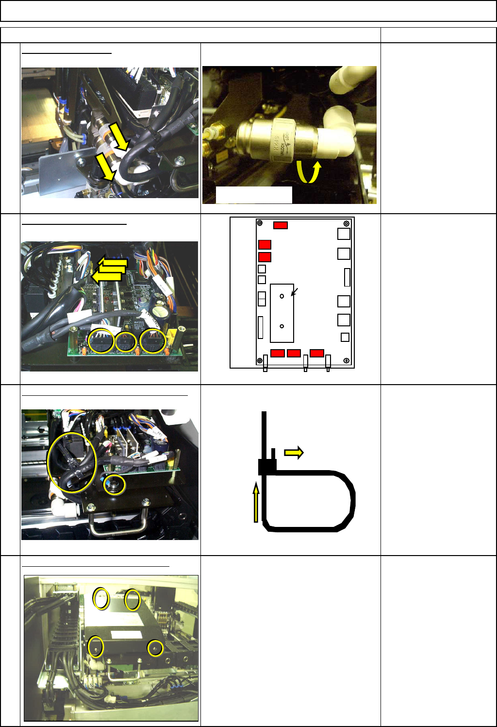
Transfer Head Assembly (8-nozzle type)
Connect the air tube.
Connect the connectors.
Secure the earth cable with a cable tie.
Phillips screwdriver #2
Round cross-head screw
M4 1 pc.
Put the upper head cover back on.
Phillip screwdriver #2
Round cross-head screw
M4 x 4
19
18
17
20
Put down the pin.
Insert.
CN13
MC15CX
Head sink
CN3
SW1
CN1
CN12
CN16
CN11
SW2
CN2
SW3
CN10
CN4
CN5
CN7
CN6
CN9
CN8
CN15
CN14
Push and turn.
EJM8A-E-SMA050301-A01-00
Page5-3-1-6
Machinery Part Replacement
Remarks
Item
Transfer Head Assembly (8-nozzle type)
Put the front head cover back on.
Phillip screwdriver #1
Round cross-head screw
M3 x 4
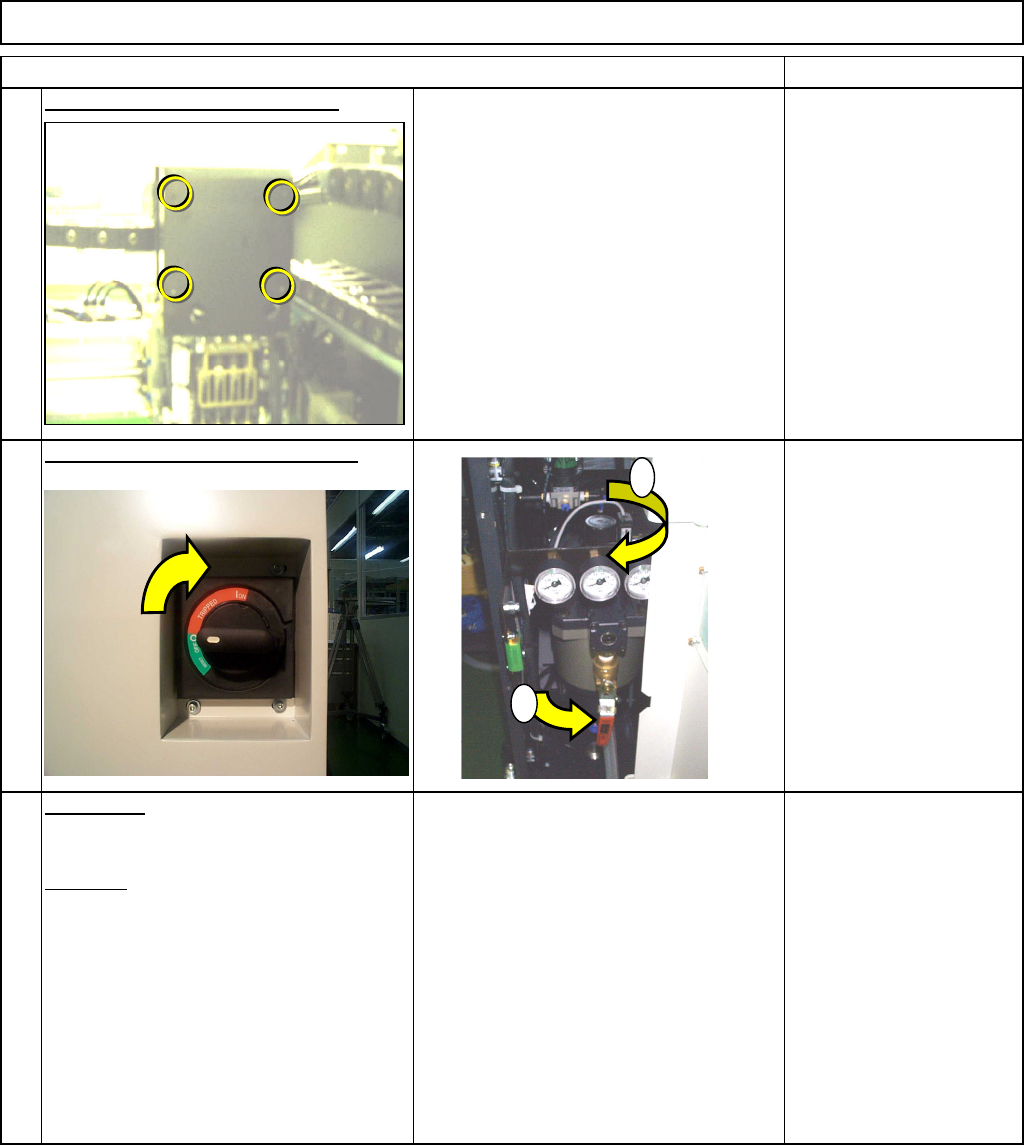
Switch on the power and air supply.
from 0.49MPa
to 0.54MPa
Adjustment
Teaching
Head Camera Adjustment
---Focus and Theta---
Board Recognition Camera
--- X and Y-axis Origin Offset
Z-axis Origin Offset
Chip Recognition Camera
and Theta-axis Origin Offset
Determining the Mounting Height and
Positioning the Board
Pickup Position
Nozzle Exchange Position
Mounting Position
Section 4-1-2
Section 4-2-2
Section 4-2-3
Section 4-2-4
Section 4-2-5
Section 4-2-8
Section 4-2-9
Section 4-2-7
22
23
21
1
2
EJM8A-E-SMA050301-A01-00
Page5-3-1-7