CM602all_EJM8AESM_Service Manual.pdf - 第454页
Board Recognition Camera - X and Y-axis Origin Offset Z-axis Origin Offset Chip Recognition Camera - Theta-axis Origin Offset Determining the Mounting Height and Positioning the Board Mounting Position Pickup Position No…
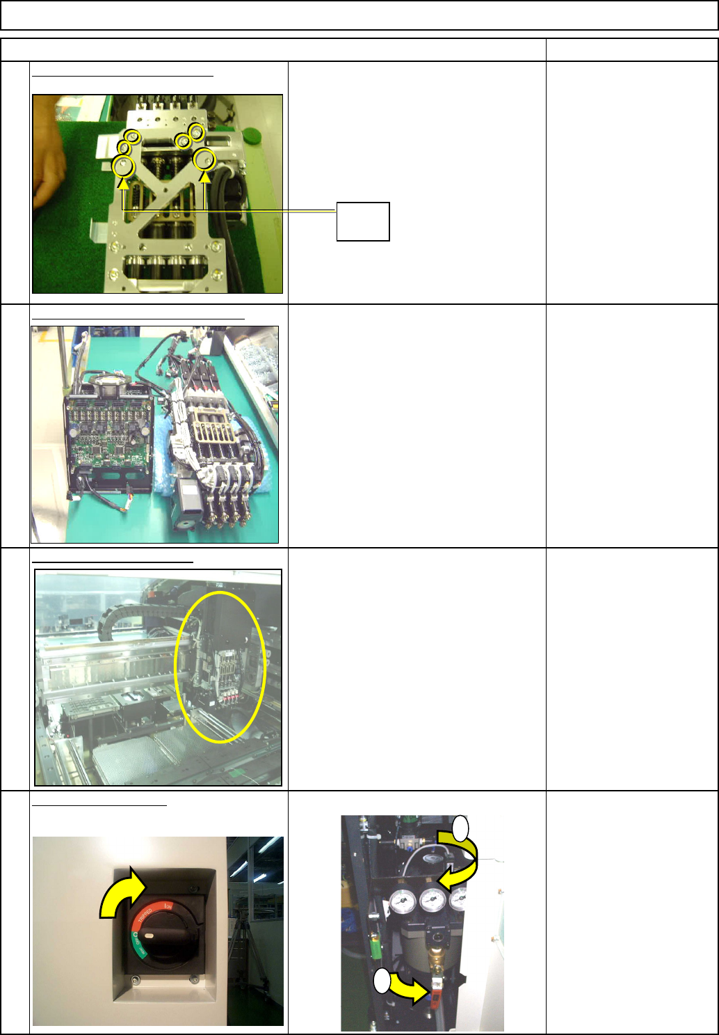
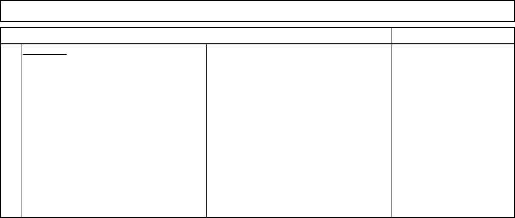
Machinery Part Replacement
Li
g
ht
T
rans
f
er-
H
ea
d
A
ssem
bl
y
(8
-nozz
l
e
type)
20
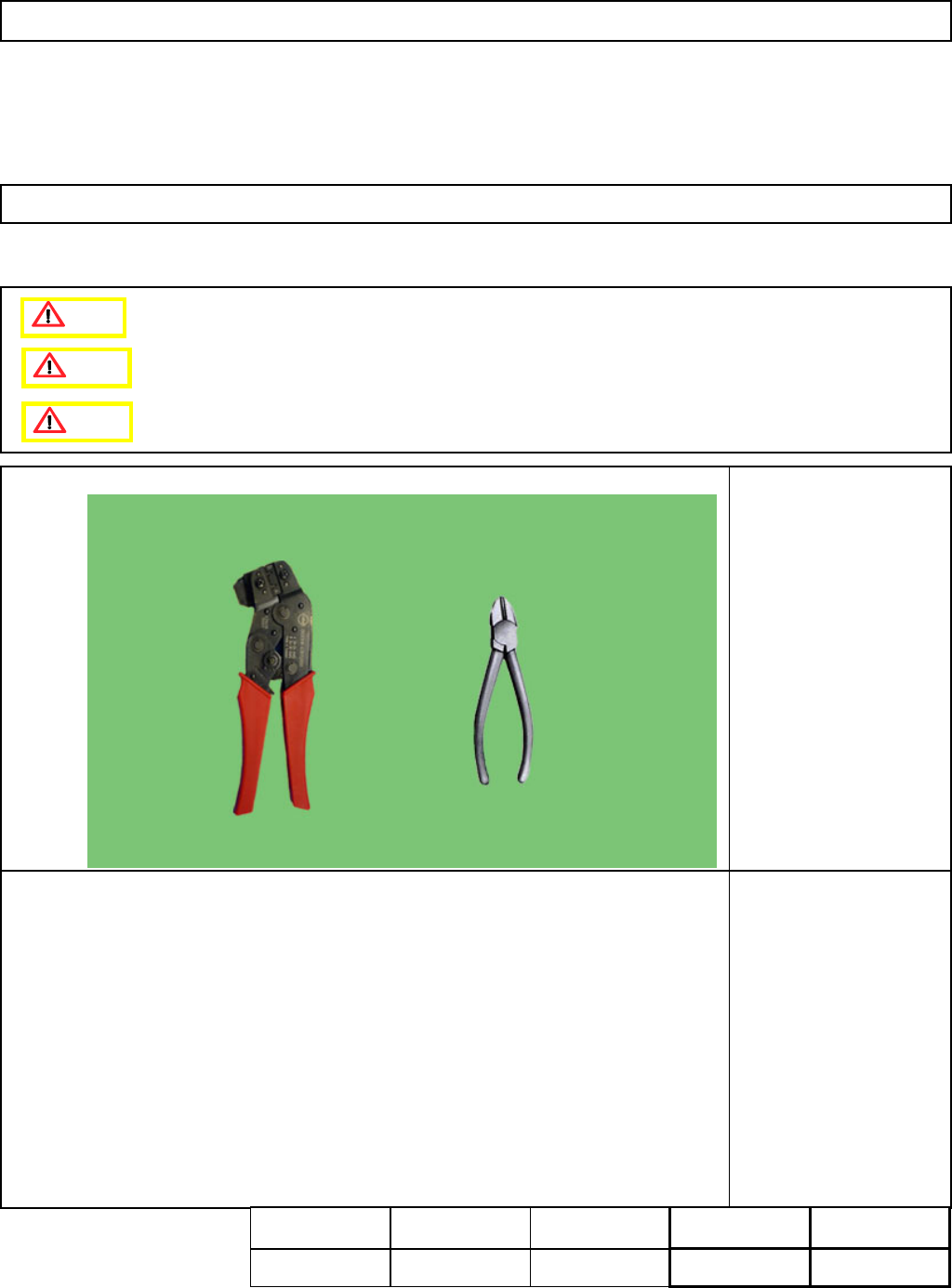
Supply power and air.
See Section 5-3-14
19
Install the head assembly.
See Section 5-3-1
See " Separating the Z-Unit from the
Board."
See "Transfer Head Assembly
Replacement."
18
Combine the Z unit and the board.
17
Put the Z-motor unit back on.
Item Remarks
Allen key 3 mm
Screw M4 4 pcs.
1
2
Dowel
pin
EJM8A-E-SMA050311-A01-00
Page 5-3-11-6
Board Recognition Camera
- X and Y-axis Origin Offset
Z-axis Origin Offset
Chip Recognition Camera
- Theta-axis Origin Offset
Determining the Mounting Height
and Positioning the Board
Mounting Position
Pickup Position
Nozzle Exchange Position
Machinery Part Replacement
Li
g
ht
T
rans
f
er-
H
ea
d
A
ssem
bl
y
(8
-nozz
l
e
type)
Item Remarks
21
Teaching:
Section 4-2-2
Section 4-2-3
Section 4-2-4
Section 4-2-5
Section 4-2-7
Section 4-2-8
Section 4-2-9
EJM8A-E-SMA050311-A01-00
Page 5-3-11-7
This section describes the procedures for placing the head cables and tubes in position.
・Tools
Nipper
Cable ties
Cramping tool
63811-2800
Wire striper
・Jig
None
Light Transfer-Head Assembly (8-nozzle type)
5-3-12 Head Cable and Tube Layout
Machinery Part Replacement
Assembly
Adjustment
60min.
Teaching
min.
Total Time Weight of
Part
Removal
Disassembly
60min.
120min.
9.3kgs
Caution
Dange
r
Warning
EJM8A-E-SMA050312-A01-00
Page 5-3-12-1