CM602all_EJM8AESM_Service Manual.pdf - 第609页
Machinery Part Replacement Remark Item 12-Nozzle Head Unit Secure the tubes with a cable tie. Nippers Connect the connectors. Connect the tube joints and lock them. Connect the camera connector. 22 23 24 21 Secure the AF…
Machinery Part Replacement
Remark
Item
12-Nozzle Head Unit
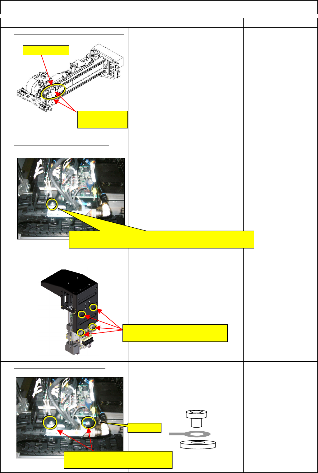
Mount the transfer head on the X beam.
• Check there are no dust or cuts on the
X-beam head plate.
• Mount the head, checking the
mounting guides on the head and the
plate sides.
• Check the dowel-pin hole on the head
side is aligned with the dowel-pin
position on the plate side.
• Check no cables are caught.
Provisionally fix the head in place.
• Hold the head by hand until the head
has been fixed provisionally.
• Put the bolts somewhere convenient so
that you can get them immediately when
you need them.
M4 x 8L
Thick washer
Tighten the head-holding bolts.
• Check the head makes a close contact
with the plate.
Allen key 5 mm
Pipe
M6 screw 4 pcs.
Tighten the earth section and the
provisionally holding bolt. • Tighten the upper provisionally holding
bolt.
• Put the earth terminal on the right, and
tighten it.
M4 x 8L 2 pcs.
Thick washer
19
17
18
20
Mounting guide
Head-positioning
dowel pins
Provisionally fix the head with the M4 x 8L screw and the thick
washer.
FG⇒Earth
Tighten them with the M4 x 8L screws
and the thick washers.
Insert an Allen key through these
positions into the head-holding bolts.
EJM8A-E-SMA051001-A01-00
Page 5-10-1-6
Machinery Part Replacement
Remark
Item
12-Nozzle Head Unit
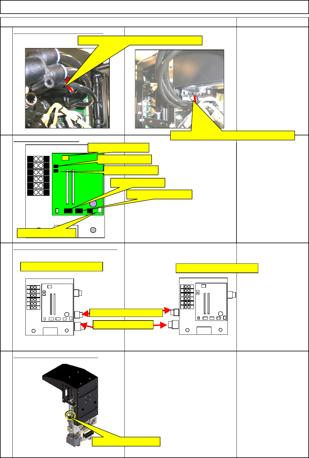
Secure the tubes with a cable tie.
Nippers
Connect the connectors.
Connect the tube joints and lock them.
Connect the camera connector.
22
23
24
21
Secure the AF and BR tubes with a cable tie.
Secure the AR and BF tubes with a cable tie.
C12-M(st,No)⇒CN12
C8-M(st,No)⇒CN8
C9-M(st,No)⇒CN9
C1-M(st,No)⇒CN1
CN11-M(st,No)⇒CN11
CN2-M(st,No)⇒CN2
Positions of AF and BR joints
Positions of AR and BF joints
Head camera connector
Vacuum joints
Vacuum release joints
EJM8A-E-SMA051001-A01-00
Page 5-10-1-7
Machinery Part Replacement
Remark
Item
12-Nozzle Head Unit
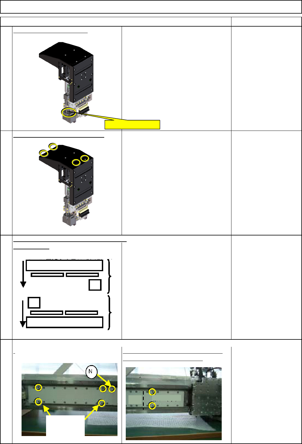
Connect the LED connector.
Put the upper head cover back on.
Phillips screwdriver #2
M4 truss 4 pcs.
the front side.
Remove the covers (large and small)
f
rom the secondary part. * Magnets are installed. Ensure safety
when working on the machine.
Cover (Large) Bolts x 4
Cover (Small) Bolts x 2
* Non-magnetic Allen
keys
Move the front and the rear beams towards
28
25
26
27
LED light connector
Rear
Front
(Large
)
Cover (Small)
Bolts
accompanying
the machine
EJM8A-E-SMA051001-A01-00
Page 5-10-1-8