CM602all_EJM8AESM_Service Manual.pdf - 第851页
This section describes the procedures for replacing the PCB-warp sensor (8-nozzle head spec.). • Tools Phillips screwdriver #1 Phillips screwdriver #2 Allen key Long/short Pipe Nipper • Jigs Height measuring jig FM-1964 …
Remarks
Option Part and Accessory Replacement
Item
PCB-Warp-Sensor Unit
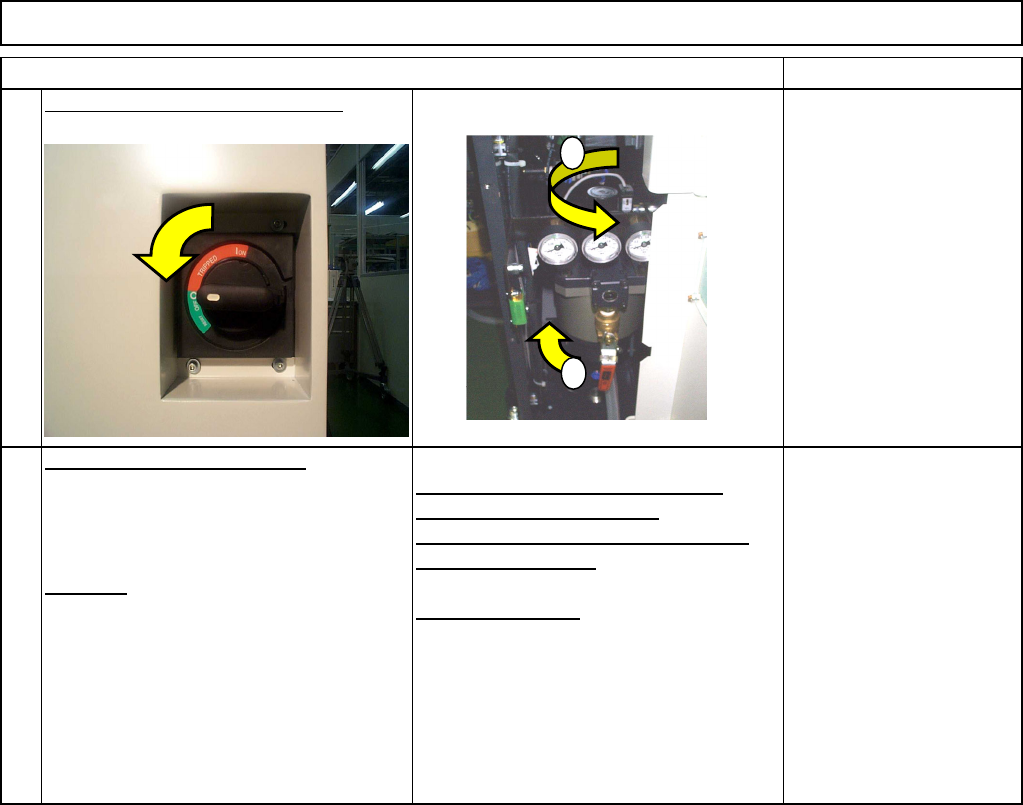
Turn on the power and air supply.
PCB-warp-sensor adjustment
Teaching
Adjusting the amplifier 0 reference
position (0-volt adjustment)
Adjusting the slant (span) of amplifier
(+2-volt adjustment)
XY offset teaching
See Section 6-5-5
17
18
1
2
EJM8A-E-SMA060502-A01-01
Page 6-5-2-6
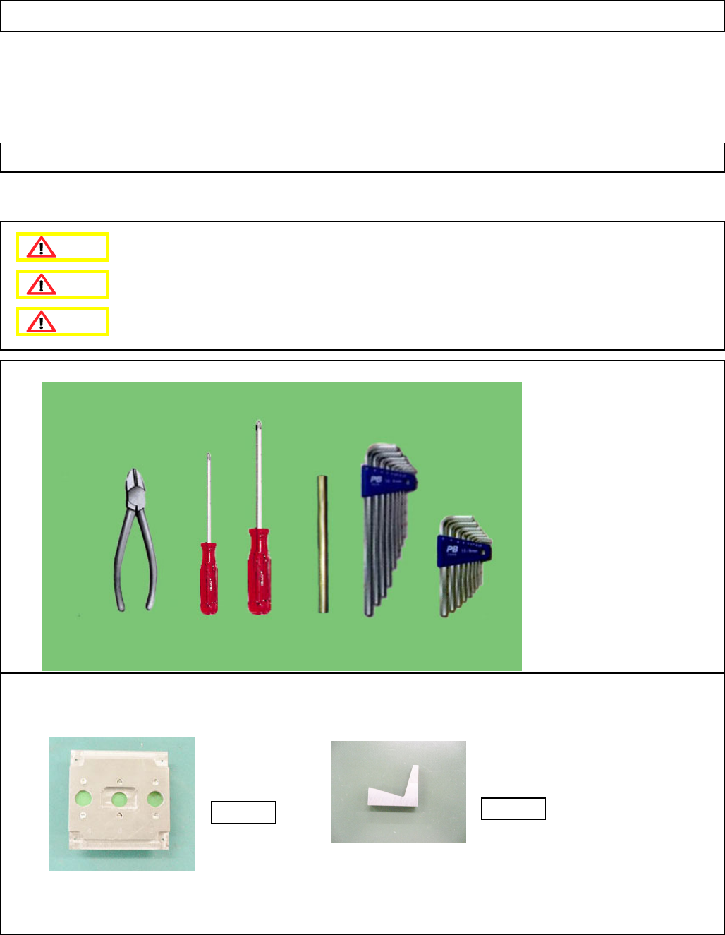
This section describes the procedures for replacing the PCB-warp sensor (8-nozzle head spec.).
• Tools
Phillips screwdriver #1
Phillips screwdriver #2
Allen key Long/short
Pipe
Nipper
• Jigs
Height measuring jig
FM-1964
Installation adjusting jig
FM-1963
Option Part and Accessory Replacemen
t
PCB-Warp-Sensor Unit
6-5-3 PCB-Warp-Sensor Replacement (8-Nozzle-Head Spec.)
FM-1964
FM-1963
Dange
r
Warning
Caution
EJM8A-E-SMA060503-A01-00
Page 6-5-3-1
Remarks
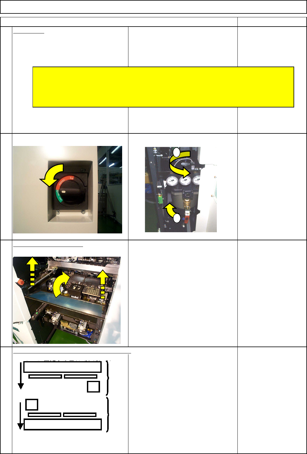
Preparation
Turn off the power and air supply.
2
Remove the feeder cover.
3
Allen key 3 mm
Screw M4 4 pcs.
4
Item
1
Move the front and rear beams towards you.
Option Part and Accessory Replacemen
t
PCB-Warp-Sensor Unit
Remove all the support pins.
* Before replacing the sensor, check no polarizing plates are attached to the head camera.
* Some of the pictures in this section of the manual are 12-nozzle-head ones; the
procedures for the 8-nozzle and 12-head nozzle heads are the same.
1
2
Rear Front
EJM8A-E-SMA060503-A01-00
Page 6-5-3-2