CM602all_EJM8AESM_Service Manual.pdf - 第452页
Li g ht T rans f er- H ea d A ssem bl y (8 -nozz l e type) Secure the holder with the insertion-type setscrew. Pull down the ball screw 25 mm. From that point, move it up with a tension gauge and check that the gauge ind…
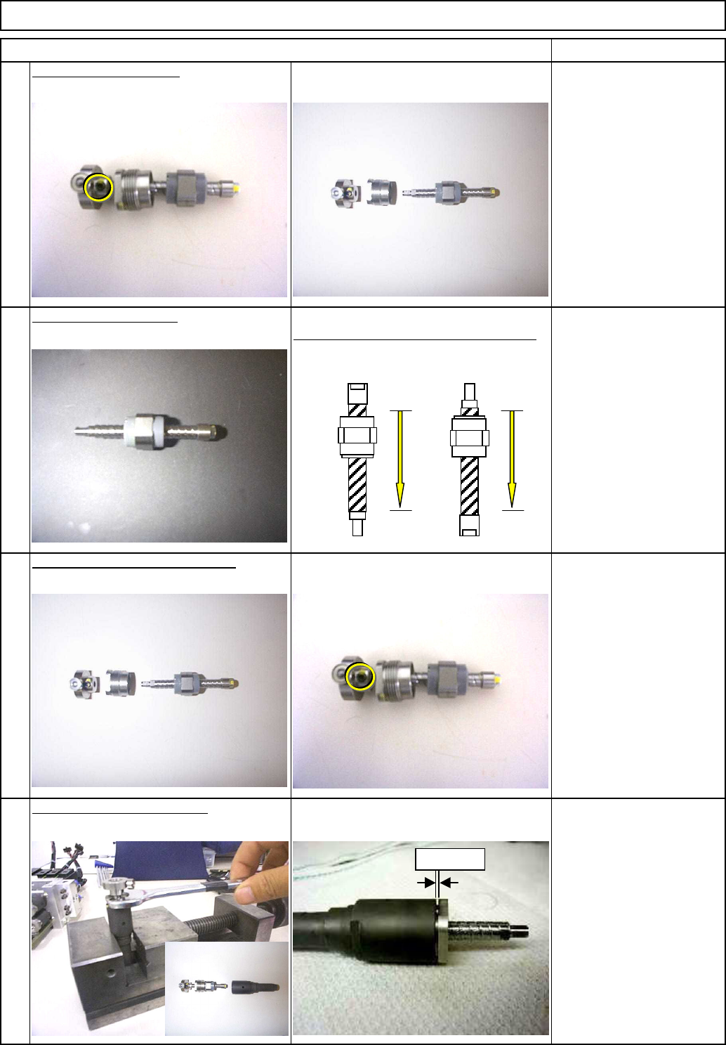
by its own weight.
Remove the ball screw.
Allen key 2 mm
Setscrew M4
Top of the screw: 0.5 mm
or less higher than the
screw hole.
Item Remarks
9
Allen key 2 mm
Setscrew M4
Top of the screw: 0.5 mm
or less higher than the
screw hole.
Check that the ball screw settles down
Machinery Part Replacement
Li
g
ht
T
rans
f
er-
H
ea
d
A
ssem
bl
y
(8
-nozz
l
e
type)
Fit the guide onto the ball screw.
Wrench 17 mm
0.2mm≦C≦0.8mm
10
11
12
Replace the ball screw.
Fit the holder, and secure it.
Gap C
EJM8A-E-SMA050311-A01-00
Page 5-3-11-4
Li
g
ht
T
rans
f
er-
H
ea
d
A
ssem
bl
y
(8
-nozz
l
e
type)
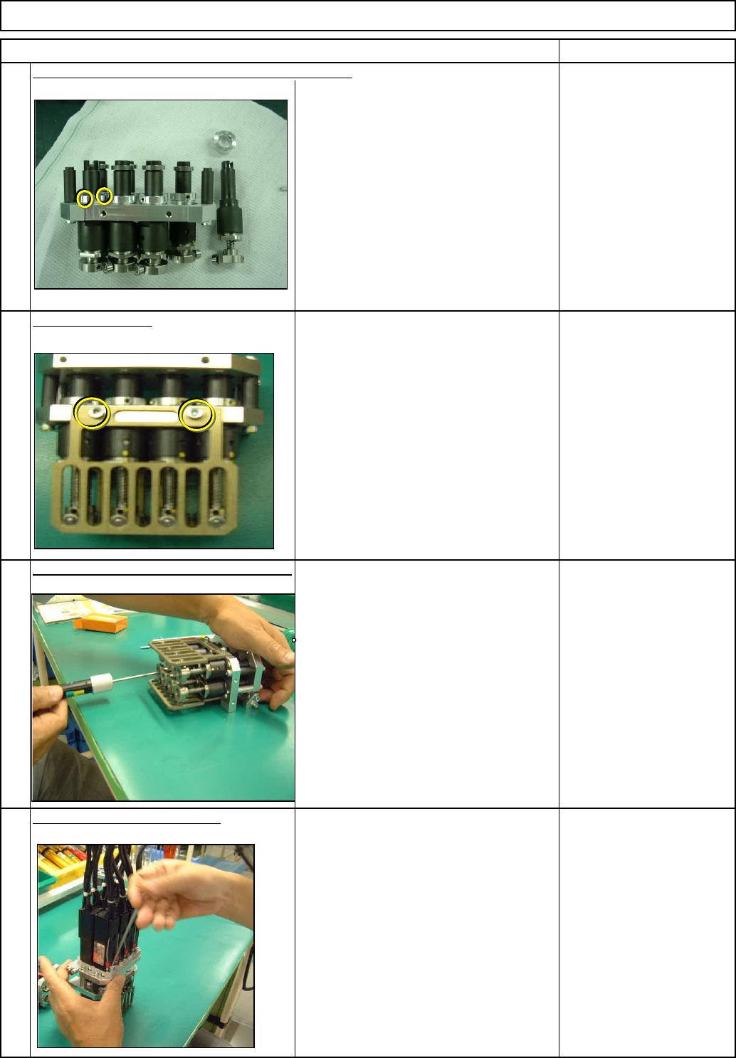
Secure the holder with the insertion-type setscrew.
Pull down the ball screw 25 mm.
From that point, move it up with a
tension gauge and check that the gauge
indicates Fu: 400cN or less.
For details, see "Z-axis Motor
Replacement."
15
Check the ball screw for slide resistance.
16
Put the Z-axis motor back on.
See Section 5-3-6.
Allen key 3 mm
Screw M4x16L 2 pcs.
Allen key 1.5 mm
Setscrew M3
Item Remarks
Machinery Part Replacement
Allen key 3 mm
Screw M4 2 pcs.
Tension gauge
Fu: 400cN or less
13
14
Fit the theta guide.
EJM8A-E-SMA050311-A01-00
Page 5-3-11-5
Machinery Part Replacement
Li
g
ht
T
rans
f
er-
H
ea
d
A
ssem
bl
y
(8
-nozz
l
e
type)
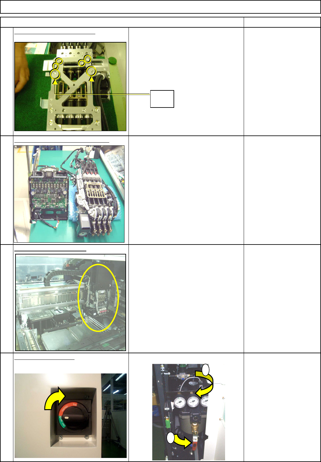
20
Supply power and air.
See Section 5-3-14
19
Install the head assembly.
See Section 5-3-1
See " Separating the Z-Unit from the
Board."
See "Transfer Head Assembly
Replacement."
18
Combine the Z unit and the board.
17
Put the Z-motor unit back on.
Item Remarks
Allen key 3 mm
Screw M4 4 pcs.
1
2
Dowel
pin
EJM8A-E-SMA050311-A01-00
Page 5-3-11-6