CM602all_EJM8AESM_Service Manual.pdf - 第425页
Machinery Part Replacement Remarks L ight Transfer-Head Assembly (8-nozzle type ) Item Install the theta motor. Allen key 3 mm Screw M4 2 pcs. Adjust the belt tension. 1-000314 Belt tension Specification 1.5kg/cm Alle…
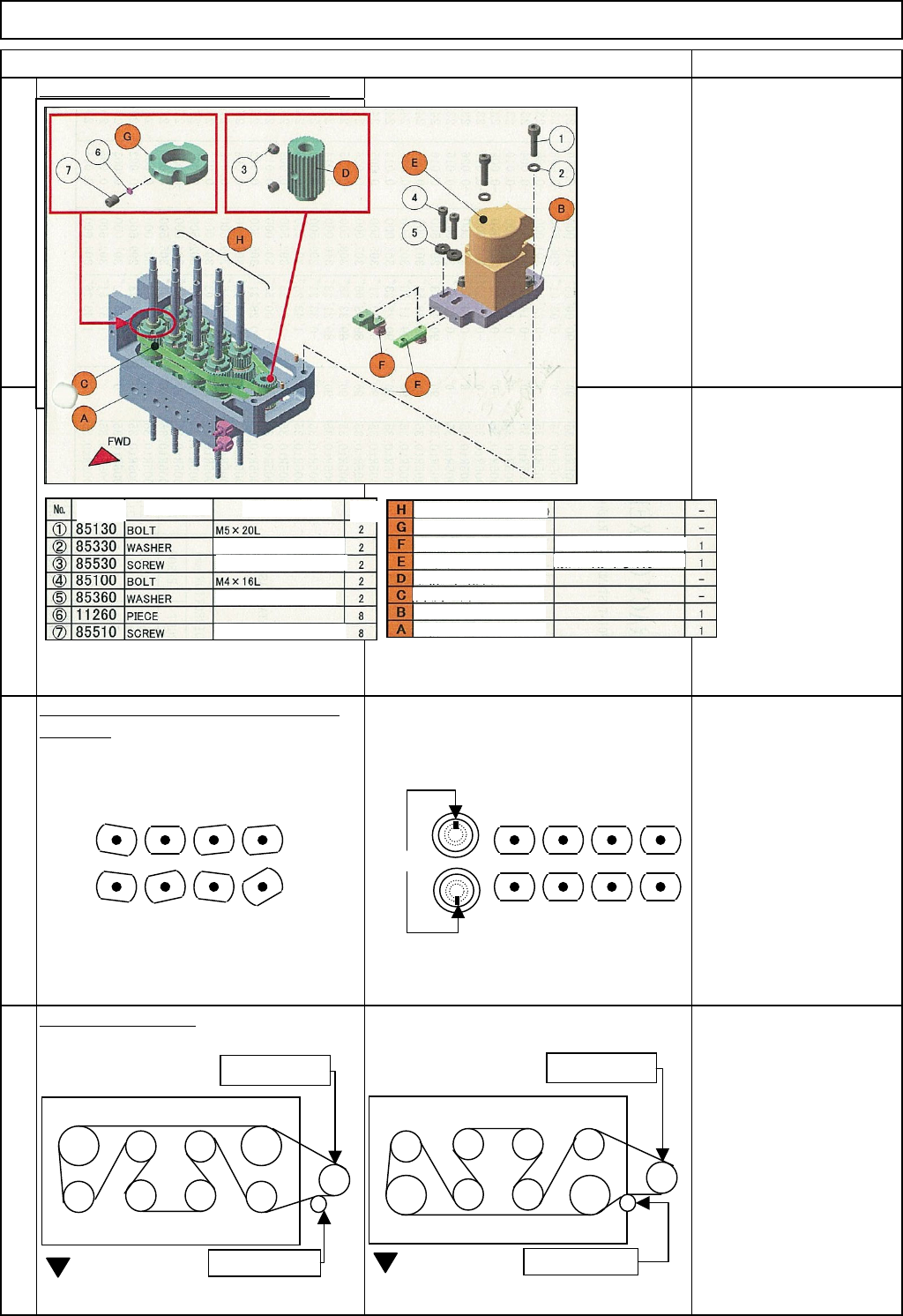
Machinery Part Replacement
Remarks
L
ight Transfer-Head Assembly (8-nozzle type
)
Item
Remove the theta motor and the belt.
Allen key 3 mm
Screw M4 2 pcs.
6
Position the nozzle holders in the theta
direction. Position the nozzle holders so that the
set-screws of the nozzle holder will face
outwards. Check by eye.
The set-screws of Nozzle
Holders 1 to 4 should be
positioned opposite those
of Nozzle Holders 5 to 8.
Re
p
lace the belts.
7
5
8
Lower belt
Motor gear
Tension pulley
FWD
Upper belt
Motor gear
Tension pulley
FWD
1
7685
4 23 1
7685
4 23
NG
OK
Set screws
Part No. Part Name
Model Qty.
Pulle
y
(
Ball spline/
g
ear
)
Small round flat washer
Hexa
g
on-hole screw
Thick washer M4
Hexa
g
on-hole screw
Nut
Adjuster B
Adjuster A
Theta
-
axis motor gear
Theta
-
axis motor base
Theta
-
axis motor housing
Timing belt
*
Flat plate
*
Bent plate
EJM8A-E-SMA050305-A01-00
Page5-3-5-3
Machinery Part Replacement
Remarks
L
ight Transfer-Head Assembly (8-nozzle type
)
Item
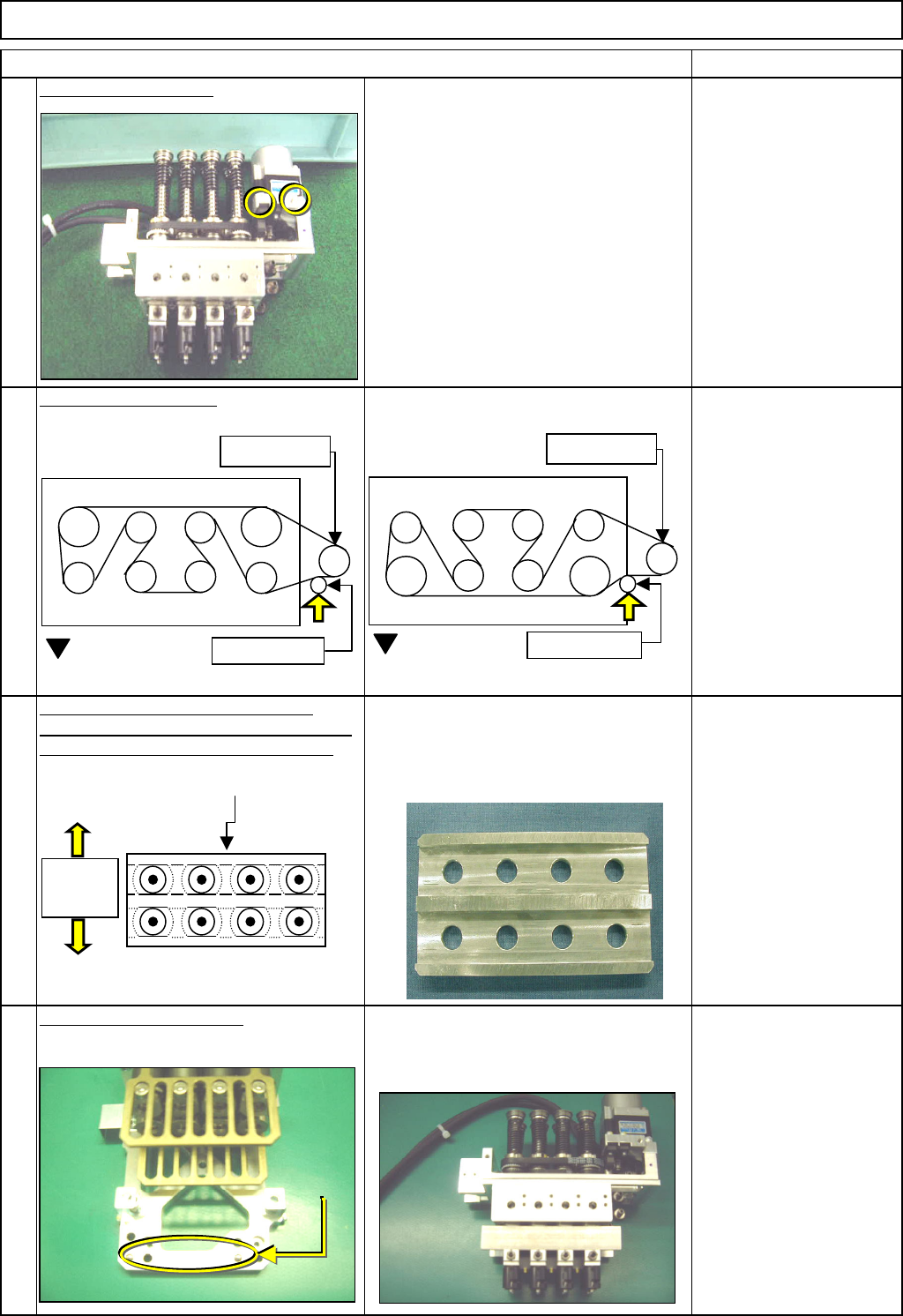
Install the theta motor.
Allen key 3 mm
Screw M4 2 pcs.
Adjust the belt tension.
1-000314
Belt tension
Specification1.5kg/cm
Allen key 3 mm
Screw M4 2 pcs.
Place the plate jig on the bottom of the
theta unit. Check that the nozzle holders are
positioned precisely in the theta direction.
Adjust the angle of each nozzle to 0°.
The set-screws of Nozzle Holders 1 to 4
should be positioned opposite those of
Nozzle Holders 5 to 8.
Nozzle theta angle
position:
Specification: +/- 0.5°
Jig: Nozzle theta adjusting
jig
Fix lightly; after installing
the head, adjust.
See Section 4-1-8.
Allen key 1.5 mm
Set-screw 2mm 8 pcs.
Put the theta unit back on.
Refer to "Theta Unit Removal." Section 5-3-13
11
9
10
12
Motor gear
Motor gear
Set-screws
should
face
td
Adjusting jig
Seen from bottom of the head
Lower belt
Tension pulley
FWD
Upper belt
Tension pulley
FWD
Dowel pin
EJM8A-E-SMA050305-A01-00
Page5-3-5-4
Machinery Part Replacement
Remarks
L
ight Transfer-Head Assembly (8-nozzle type
)
Item
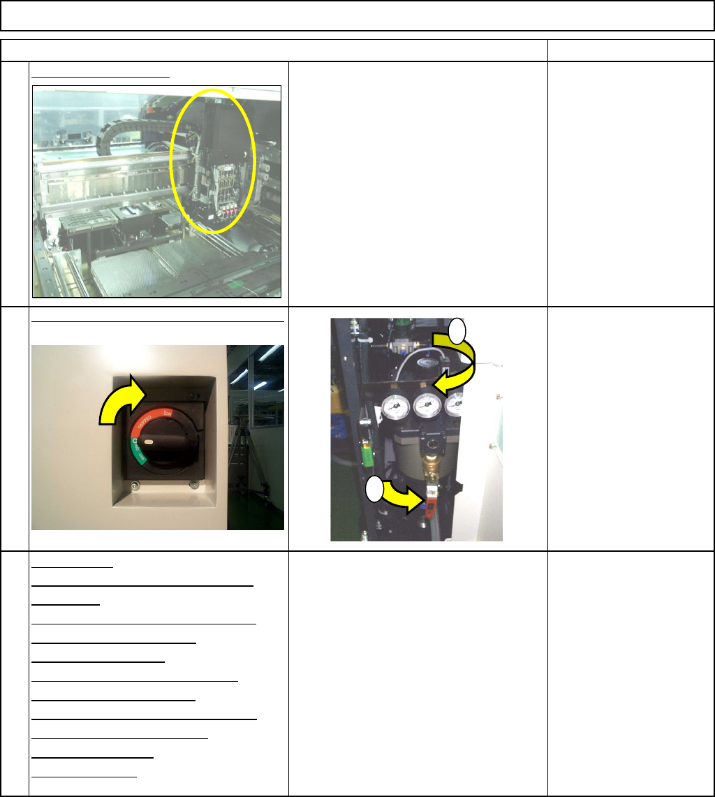
Install the head unit.
Refer to "Head Assembly Replacement." Section 5-3-1
Switch on the main power and air supply.
From 0.49MPa
to 0.54MPa
Ad
j
ustment:
Nozzle Holder Angle Adjustment
Teaching:
Board Recognition Camera --- X
and Y-axis Origin Offset
Z-axis Origin Offset
Chip Recognition Camera and
Theta-axis Origin Offset
Determining the Mounting Height
and Positioning the Board
Mounting Position
Pickup Position
Nozzle Exchan
g
e Position
Section 4-1-8
Section 4-2-2
Section 4-2-3
Section 4-2-4
Section 4-2-5
Section 4-2-7
Section 4-2-8
Section 4-2-9
13
14
15
1
2
EJM8A-E-SMA050305-A01-00
Page5-3-5-5