CM602all_EJM8AESM_Service Manual.pdf - 第982页
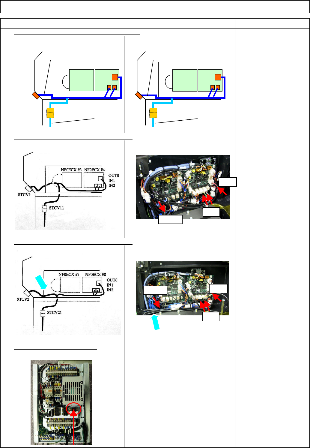
Connect the power connector. Be careful of the direction when connecting it. Allen key 2.5 mm Screw M3 x 8 4 pcs. Connect the Signal Cable 1 connector. Be careful of the direction when connecting it. Allen key 3 mm Screw…
Layout of Signal Cable 2 to AR Left Ring I/O
Layout of Signal Cable 2 to BR Left Ring I/O
Connect the power cable to the
rear side of the power unit.
Power unit 1 TYR.P1
Power unit 2 TYR.P2
91060:
A stage tray
communication cable 2
91070:
B stage tray
communication cable 2
Tray Shuttle Tray
Connect the transfer unit communication cable.
Remarks
22
23
21
24
Item
Remove the upper side
cover
Secure the cable,
positioning it outside the
frame.
NF0ECX#4
91060
STCV11
NF0ECX#3
91030
STCV1
OUT0
IN1
IN2
STCV21
NF0ECX#7NF0ECX#8
91070
91040
STCV2
OUT0
IN1
IN2
STVC11
IN2/1
OUT0
STVC21
IN2/1
OUT0
EJM8A-E-SMA070117-A01-00 Page 7-1-17-7
Connect the power connector.
Be careful of the direction when
connecting it.
Allen key 2.5 mm
Screw M3 x 8 4 pcs.
Connect the Signal Cable 1 connector.
Be careful of the direction when
connecting it. Allen key 3 mm
Screw M4 x 8 4 pcs.
Connect the signal cable to Power Unit 1.
Connect the signal cable to Power Unit 2.
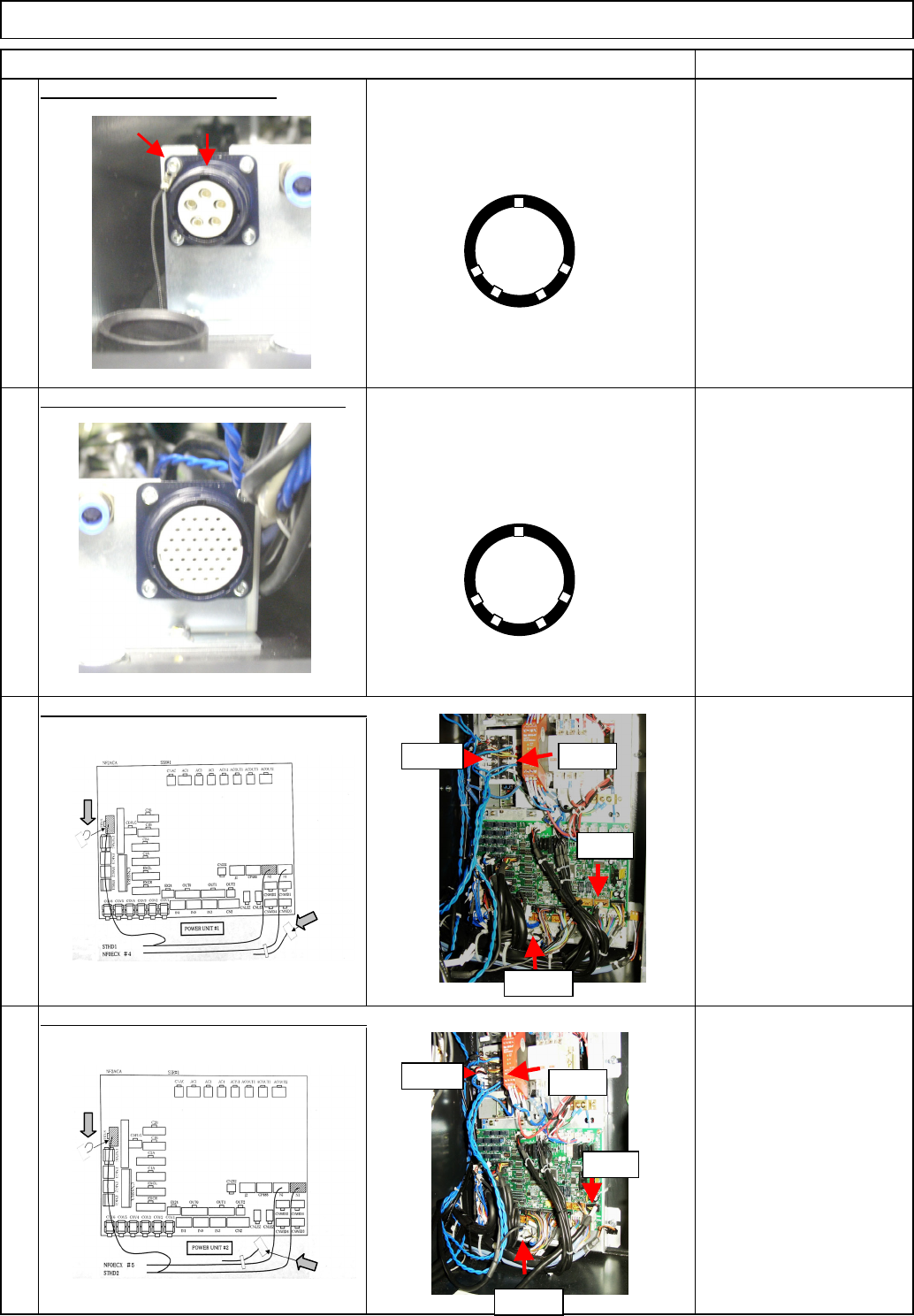
(2) Standard cables N2 to
N5 are not used.
Shuttle Tray
28
26
25
Tray
Item Remarks
27
(1) Secure the unused
short connector with a
cable tie.
(1) Secure the unused
short connector with a
cable tie.
Tie the cap strap to the upper left screw
as shown at left.
(2) Standard cables N2 to
N5 are not used.
UP
(1)
(2)
R2A+V R2A-V
TRY.EA
N2-N5
R2B+V
R2B-V
TRY.EB
N1-N9
(1)
(2)
UP
EJM8A-E-SMA070117-A01-00 Page 7-1-17-8
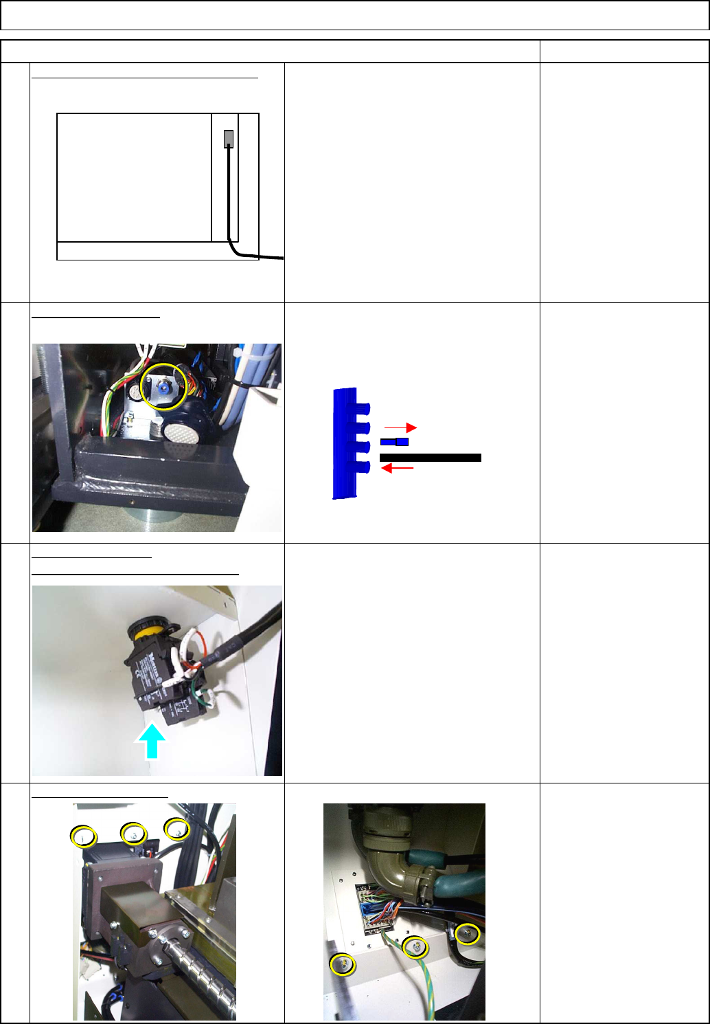
Connect the signal cable to the CPU.
Connect it to NF0FCX CN13.
Fix the cover in place.
Tray
Phillips screwdriver #2
Allen key 3 mm
M4 button head screw
4 pcs.
M4 screw 6 pcs.
31
Replace the cover.
Install the emergency stop button.
32
Item Remarks
Shuttle Tray
29
30
Connect the air tube.
CPU BOX
EJM8A-E-SMA070117-A01-00 Page 7-1-17-9