CM602all_EJM8AESM_Service Manual.pdf - 第226页
Prepare jigs, feeders, boards, etc. 1 to 10 Adjust the pickup position. 11 to 12 If a pickup error occurs, accurate teaching may not be carried out. Warm up the machine. 13 to 17 Test run of machine Teach "Shadow&qu…
s
4-2-7 Mounting Position
Maintenance Adjustment
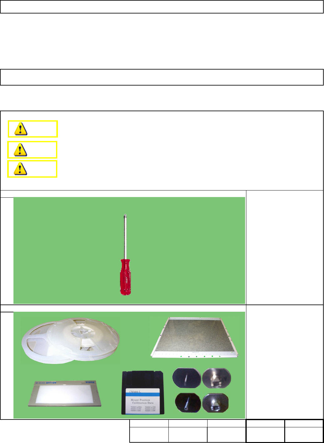
Light Transfer-Head Assembly (8 nozzles)
This section describes the procedures for teaching the mounting position.
Total time Part weight
Mounting position
correcting data
Light Box
Glass board
(240x215 TH: 2.4)
Component 1005R 2 pcs.
Component 0603R 2pcs.
Nozzle 110 16 pcs.
Nozzle 205A 16 pcs.
Double-sided tape
Phillips screwdriver #2
Min. Min.
kgs
.
90 Min.Min.
Removal/Disassembly
90
Tool
Jig
Teaching
・Jigs
・Jigs
Assembly/Adjustment
Dange
r
Warning
Caution
EJM8A-E-SMA040207-A01-00
Page 4-2-7-1
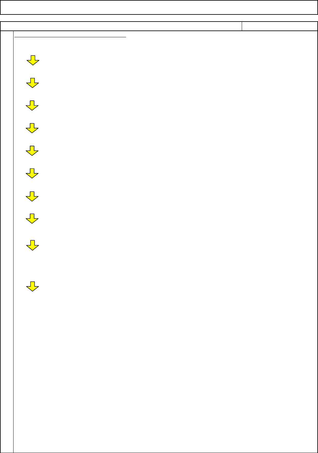
Prepare jigs, feeders, boards, etc. 1 to 10
Adjust the pickup position. 11 to 12 If a pickup error occurs, accurate teaching
may not be carried out.
Warm up the machine. 13 to 17 Test run of machine
Teach "Shadow" mounting position. 18 to 24 Teach. Place components. Recognize with
head camera. Specify offset (Auto)
Precision test (Placement accuracy test) (1) 25 to 30 Place components. Recognize with head
camera. Measure placement results.
Check precision (accuracy) (1) 31 to 32 Display the precision data.
Enter mounting position offset. 37 Calculate offset from the precision
data and enter it into "Mount position" of
Machine Parameters manually.
Precision test (Placement accuracy test) (2) 25 to 30 Test after entering the mounting position
offset.
Check precision (accuracy) (1) 31 to 32 Display the precision data.
Cpk displayed on CM602 monitor:
Guidance: 1.8 or more
(Equivalent to Cpk 1.5 or more with Panasonic
tester.)
Teach "Direct" mounting position
Prepare jigs, feeders, a board, etc. 33 to 36
Follow the "Shadow" teaching procedures.
Maintenance Adjustment
1
Flow Chart of Mounting Position Teaching
ITEM
Light Transfer-Head Assembly (8 nozzles)
REMARKS
EJM8A-E-SMA040207-A01-00
Page 4-2-7-2
Since the feeder cover is left removed,
block the "Tape float sensor 1" with tape
or an equivalent tool when installing the
cart.
Install the feeder change cart.
Maintenance Adjustment
3
2
See Section "5-8-1. Feeder
Cart Installation and
Removal"
Tape
4
ITEM
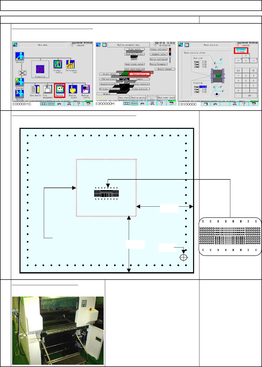
Place double-sided transparent tape on the glass board.
Double-sided tape
240×215 TH-2.4 glass
board
REMARKS
Enter "0" into "Mount position offset."
Light Transfer-Head Assembly (8 nozzles)
Components will be placed here.
Tape size 80 x 80 approx.
80mm
80mm
Origin
EJM8A-E-SMA040207-A01-00
Page 4-2-7-3