CM602all_EJM8AESM_Service Manual.pdf - 第369页
28 Check the position of the head camera. See Section 4-1-2 "Head Camera Adjustment --- Focus and Theta." See Section 4-1-6 "Leveling the Support Plate." 27 Switch on the power and the air supply. Fro…
Machine Part Replacement Main Body
24
Remove the Z clamp plates from the
conveyor.
Allen key 3 mm
Special screw M4 x 8
16 pcs.
23
Put the head back on.
For High-Speed Head, see
Section 5-3-1
"Transfer Head Assembly
Replacement."
For Multi-Purpose Head,
see Section 5-5-2
"Replacing a Set of Head
Units."
22
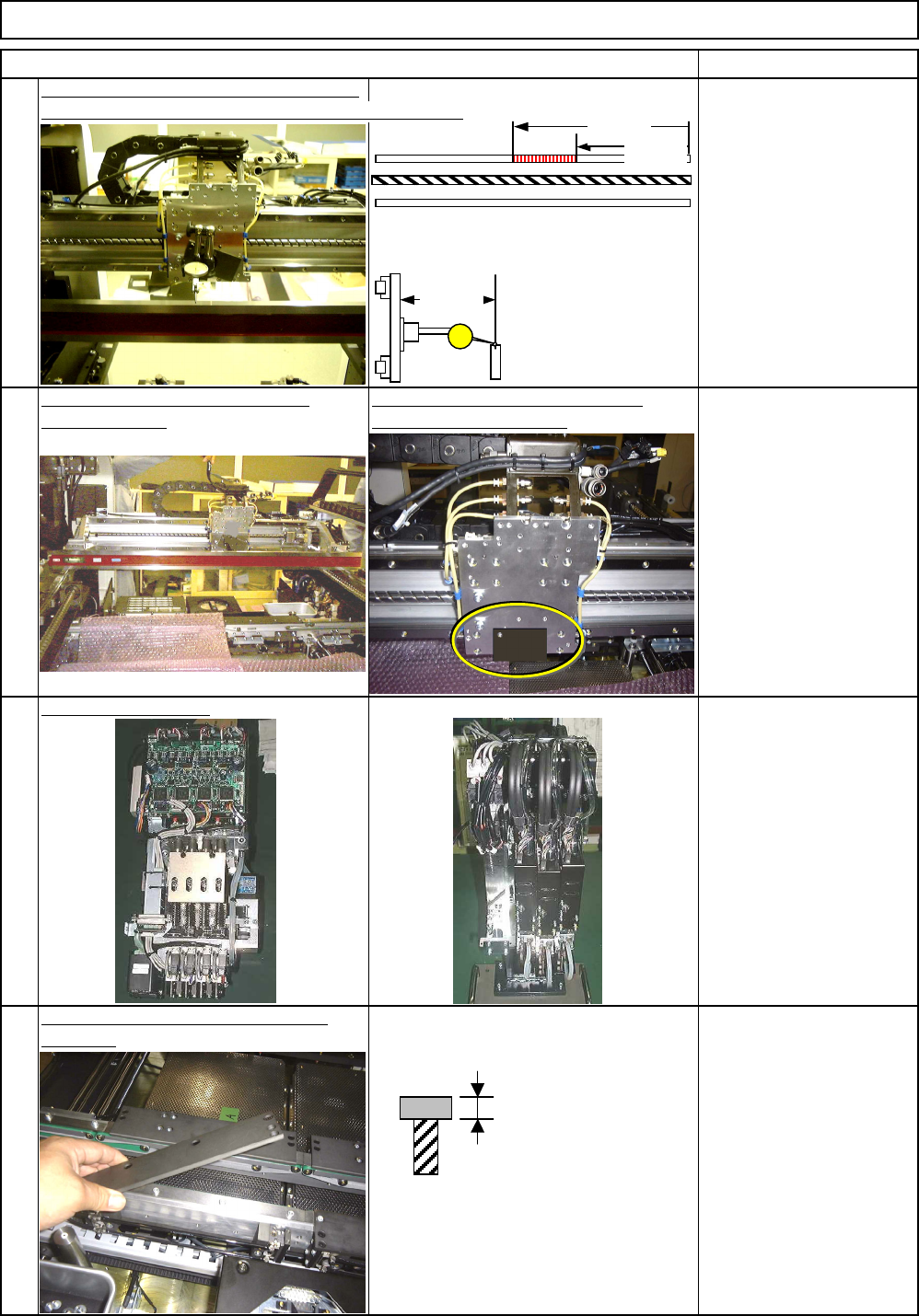
Remove the straight edge from the Remove the iron plate on which the
Y-axis linear rail. magnetic stand is placed.
Straight edge 1500 mm
Iron plate holding the
magnetic stand
Allen key 3 mm
Screw M4 1 pc.
21
After placing the head plate, measure the
Specifications:
Parallelism of whole length
of the linear rail: 0.02 mm
or less
Z: 0.005 mm or less
Magnetic stand
Dial gauge
parallelism of the specified section of the straight edge.
項目(ITEM) 備考(REMARK)
340 mm
430 mm
Z: Parallelism when the dowel pin is moved
from the rightmost end by 340mm and 430 mm.
105 mm
Z
2.7 mm
EJM8A-E-SMA050109-A01-00
Page 5-1-9-7
28
Check the position of the head camera.
See Section 4-1-2 "Head
Camera Adjustment ---
Focus and Theta."
See Section 4-1-6 "Leveling
the Support Plate."
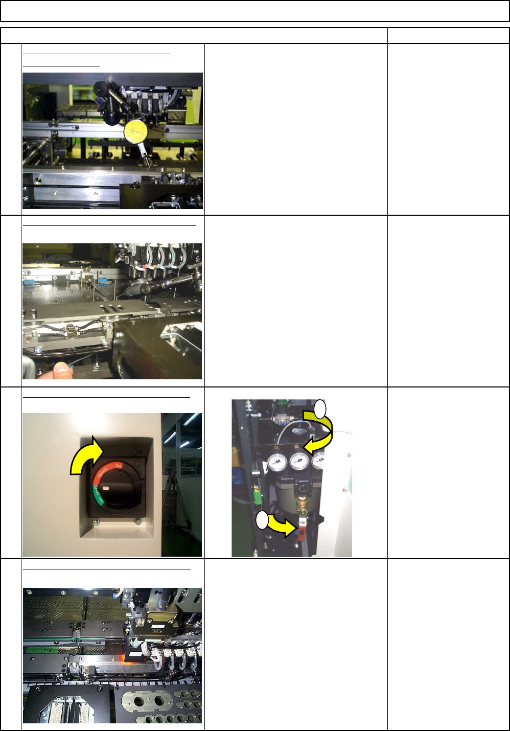
27
Switch on the power and the air supply.
From 0.49MPa
to 0.54MPa
25
26
項目(ITEM) 備考(REMARK)
Machine Part Replacement Main Body
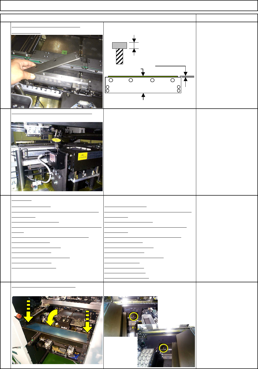
Check the parallelism of the board
transfer conveyor.
See Section 4-1-
4"Parallelism of Board
Transfer Conveyors
Check the levelness of the support plate.
1
2
EJM8A-E-SMA050109-A01-00
Page 5-1-9-8
Teaching
29
Put the Z clamp plates back on
the conveyor.
項目(ITEM) 備考(REMARK)
Machine Part Replacement Main Body
Allen key 3 mm
Special screw M4 x 8
16 pcs.
30
Check the height of the lead checker.
For "Multi-Purpose" head
only
See Section 4-1-9 "Lead
Checker Height
Adjustment."
31
High-Speed Head Multi-purpose Head
4-2-2 "Board Recognition Camera --- X and Y-axis
Origin Offset"
4-2-3 "Z-axis Origin Offset"
4-2-4 "Chip Recognition Camera - Theta-axis Origin
Offset"
4-2-5 "Determining the Mounting Height and
Positioning the Board"
4-2-6 "XY Plane Calibration"
4-2-8 "Pickup position"
4-2-9 "Nozzle Exchange Position"
4-2-10 "Light Intensity"
4-2-7 "Mounting Position"
4-3-2 "Board Recognition Camera --- X and Y-axis
Origin Offset"
4-3-3 "Z-axis Origin Offset"
4-3-4 "Chip Recognition Camera --- Theta Axis
Origin Offset"
4-3-5 "Determining the Mounting Height and
Positioning the Board"
4-3-6 "XY Plane Calibration"
4-3-8 "Pickup Position"
4-3-9 "Nozzle Exchange Position"
403-10 "Load Head"
4-3-11 "Lead Checker"
4-3-12 ""Light Intensity"
4-3-7 "Mounting Position"
32
Put the feeder cover back on.
Phillips screwdriver #2
Screw M4 2 pcs.
2.7 mm
0.3 to 0.5 mm
Z clamp plate
Transfer
conveyor belt
EJM8A-E-SMA050109-A01-00
Page 5-1-9-9