CM602all_EJM8AESM_Service Manual.pdf - 第189页
3 4 Phillips screwdriver #2 Allen key 3 mm Screw M4 2 pcs. M4x10mm 3 pcs. Allen key 3 mm Screw M4x10 8 pcs. Remarks Remove the feeder cover and the chute. Maintenance Adjustment 2 1 Item Main Body Beam Remove the Z clamp…
Main Body BeamMaintenance Adjustment
This section describes the procedures for leveling the board transfer conveyors.
4-1-14 Levelness of Board Transfer Conveyors
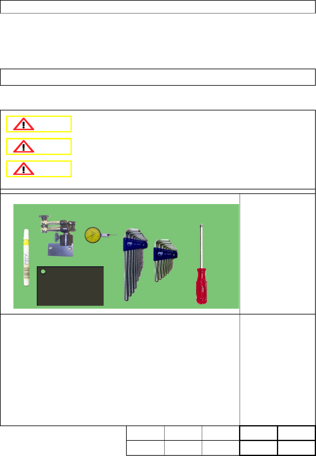
Phillips screwdriver #2
Dial gauge
Iron plate
Allen key 3 mm
Allen key 4 mm
Box wrench 7 mm
Magnetic stand
Magic marker
None
Teaching Total Time
Kgs
.
・Tools
・Jigs
Weight of
Par
t
20 min. 20 min.
Removal
Disassembly
A
ssembl
y
Adjustment
min.
40
min
.
Dange
r
Warning
Caution
EJM8A-E-SMA040114-A01-00
Page 4-1-14-1
3
4
Phillips screwdriver #2
Allen key 3 mm
Screw M4 2 pcs.
M4x10mm 3 pcs.
Allen key 3 mm
Screw M4x10 8 pcs.
Remarks
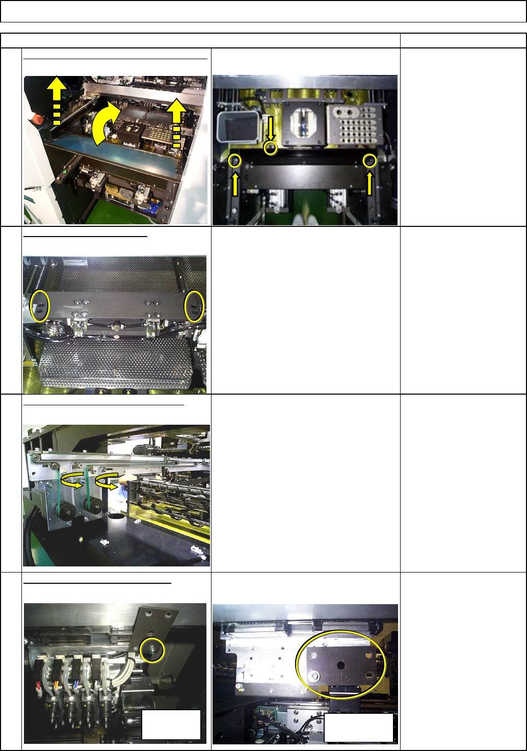
Remove the feeder cover and the chute.
Maintenance Adjustment
2
1
Item
Main Body Beam
Remove the Z clamp plate.
Remove the transfer conveyor belt.
Place the iron plate on the head.
Allen key 3 mm
Screw M4 1 pc.
High-speed
head
Multi-purpose
head
EJM8A-E-SMA040114-A01-00
Page 4-1-14-2
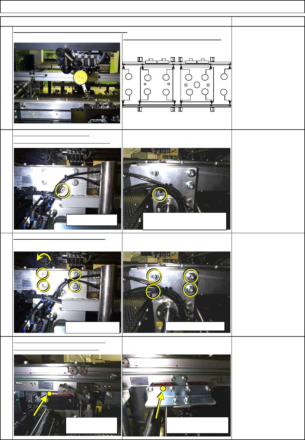
Points (1) to (12).
Allen key 3 mm
Magic marker
Screw M4 2 pcs.
The fixed-conveyor eccentric pin is
placed at the back of the sensor.
8
Main Body Beam
Item Remarks
5
Maintenance Adjustment
All sections except board clamp
section:
Levelness: ±0.1 mm
Board clamp section:
Levelness:
within ±0.02 mm
Reference height:
169.35±0.1 mm
(when surface table is used)
Dial gauge, Magnetic stand
7
Allen key 4 mm
Screw M5 4 pcs.
6
Conveyor Height Adjustment
Loosen the eccentric pin holding nut.
Box wrench 7 mm
Employing (8) as reference, measure
Loosen the conveyor holding bolts.
Check the levelness of the fixed clamp rail.
Fixed conveyor
(Board detection)
Fixed conveyor
(Stopper section)
Fixed conveyors Movable conveyors
Fixed conveyor
Movable conveyor
(Left and Right: symmetric)
11
4
2
8
9
53
10 12
1
7
6
EJM8A-E-SMA040114-A01-00
Page 4-1-14-3