CM602all_EJM8AESM_Service Manual.pdf - 第193页
Be careful not to deform the shadin g p lates. A deformed shadin g p late ma y cause a reco g nition error. Removal/Disassembly Part Weight kg Phillips screwdriver #2 Allen key 3 mm Allen key 4 mm Cloth Ruler 150 mm Tota…
Maintenance Adjustment Main Body Beam
Item Remarks
15
Phillips screwdriver #2
Allen key 3 mm
Screw M4 2 pcs.
M4x10 3 pcs.
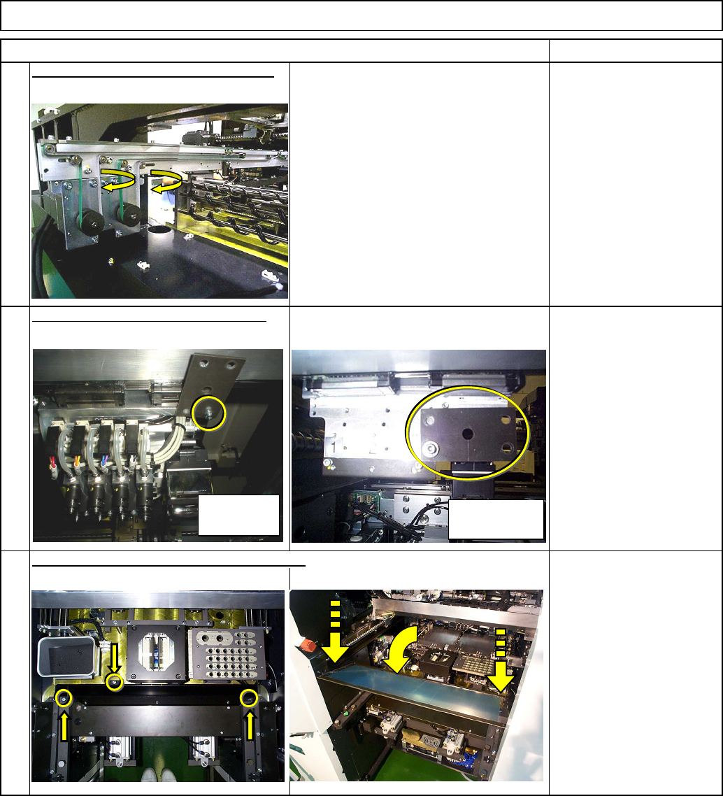
Put the feeder cover and the chute back on.
14
Remove the iron plate from the head.
Allen key 3 mm
Screw M4 1 pc.
13
Put the transfer conveyor belt back on.
High-speed
head
Multi-purpose
head
EJM8A-E-SMA040114-A01-00
Page 4-1-14-5
Be careful not to deform the shadin
g
p
lates.
A
deformed shadin
g
p
late ma
y
cause a reco
g
nition error.
Removal/Disassembly
Part Weight
kg
Phillips screwdriver #2
Allen key 3 mm
Allen key 4 mm
Cloth
Ruler 150 mm
Total Time
Min.
2
Min.
-
Min.
2
Min.
Maintenance Adjustment Main Body Beam
Assembly/Adjustment
Teaching
• Jigs
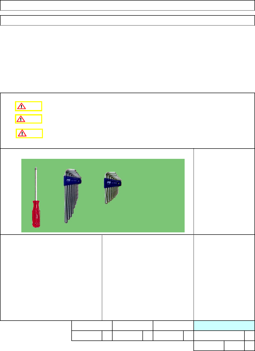
4-1-15 Chip Camera Cover Glass Cleaning (Inside)
• This section describes the procedures for cleaning the chip camera cover glass.
• Tools
Caution
Dange
r
Warning
EJM8A-E-SMA040115-A01-00
Page 4-1-15-1
1. Turn OFF the power.
Phillips screwdriver
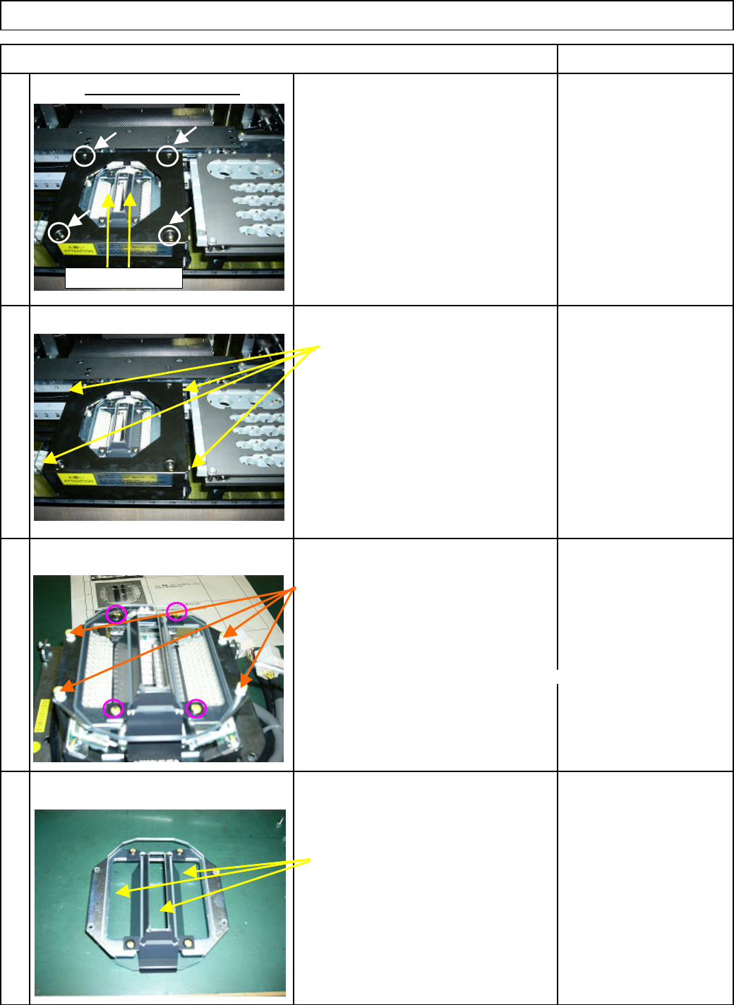
2. Remove the four
(
4
)
Philli
p
s screws
1 from the line camera cover.
Remove the hexa
g
on screws from th
e
A
llen ke
y
3 mm
sides of the line-camera cover.
2
A
llen ke
y
3 mm
Remove the four
(
4
)
hexa
g
on screws.
3
* Do not remove the Philli
p
s
screws circled at left!
Otherwise ad
j
ustment is re
q
uired.
Cloth
A
lcohol
Remove dust dirt
,
etc. from the
cover
g
lass with cloth
,
a cotton
4 bud
,
brush or an e
q
uivalent tool.
Remove the black cover.
Remove the cover glass.
Item Remark
Maintenance Adjustment Main Body Beam
Shading plates
EJM8A-E-SMA040115-A01-00
Page 4-1-15-2