CM602all_EJM8AESM_Service Manual.pdf - 第537页
Machinery Part Replacement Z Unit (3-nozzle type) Phillips screwdriver #2 Screw M3 2 pcs. Tools and Specifications Tools and Specifications 5 screws. Phillips screwdriver #2 Screw M3 2 pcs. Allen key 2.5 mm Screw M3 2 pc…
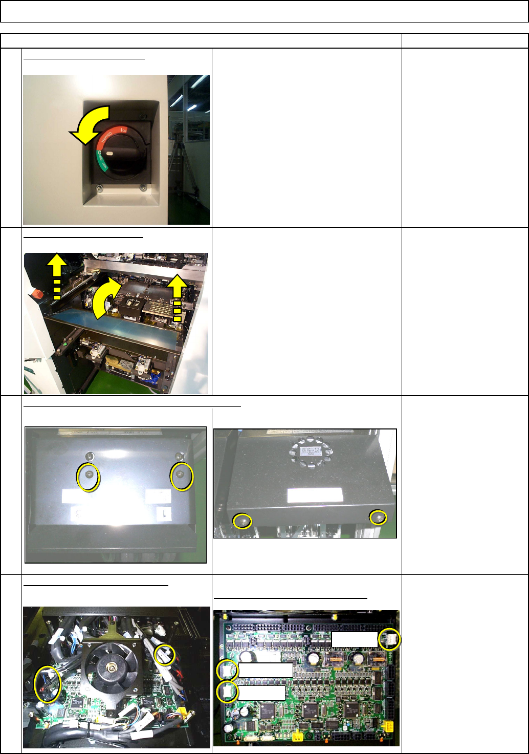
Z Unit (3-nozzle type)
Tools and Specifications
3
White connectors: Z origin sensor
4
Tools and Specifications
Item Remarks
Tools and Specifications
Phillips screwdriver #1
Phillips screwdriver #2
Screw M3 2 pcs.
M4 2 pcs.
Phillips screwdriver #2
Screw M4 2 pcs.
Tools and Specifications
Remove the top cover from the head assembly.
Remove the sensor connectors.
2
1
Remove the feeder cover.
Switch off the main power.
Machinery Part Replacement
CN10: Z1
CN9: Z2
CN7: Z3
EJM8A-E-SMA050508-A01-00
Page 5-5-8-2
Machinery Part Replacement
Z Unit (3-nozzle type)
Phillips screwdriver #2
Screw M3 2 pcs.
Tools and Specifications
Tools and Specifications
5
screws.
Phillips screwdriver #2
Screw M3 2 pcs.
Allen key 2.5 mm
Screw M3 2 pcs.
Item Remarks
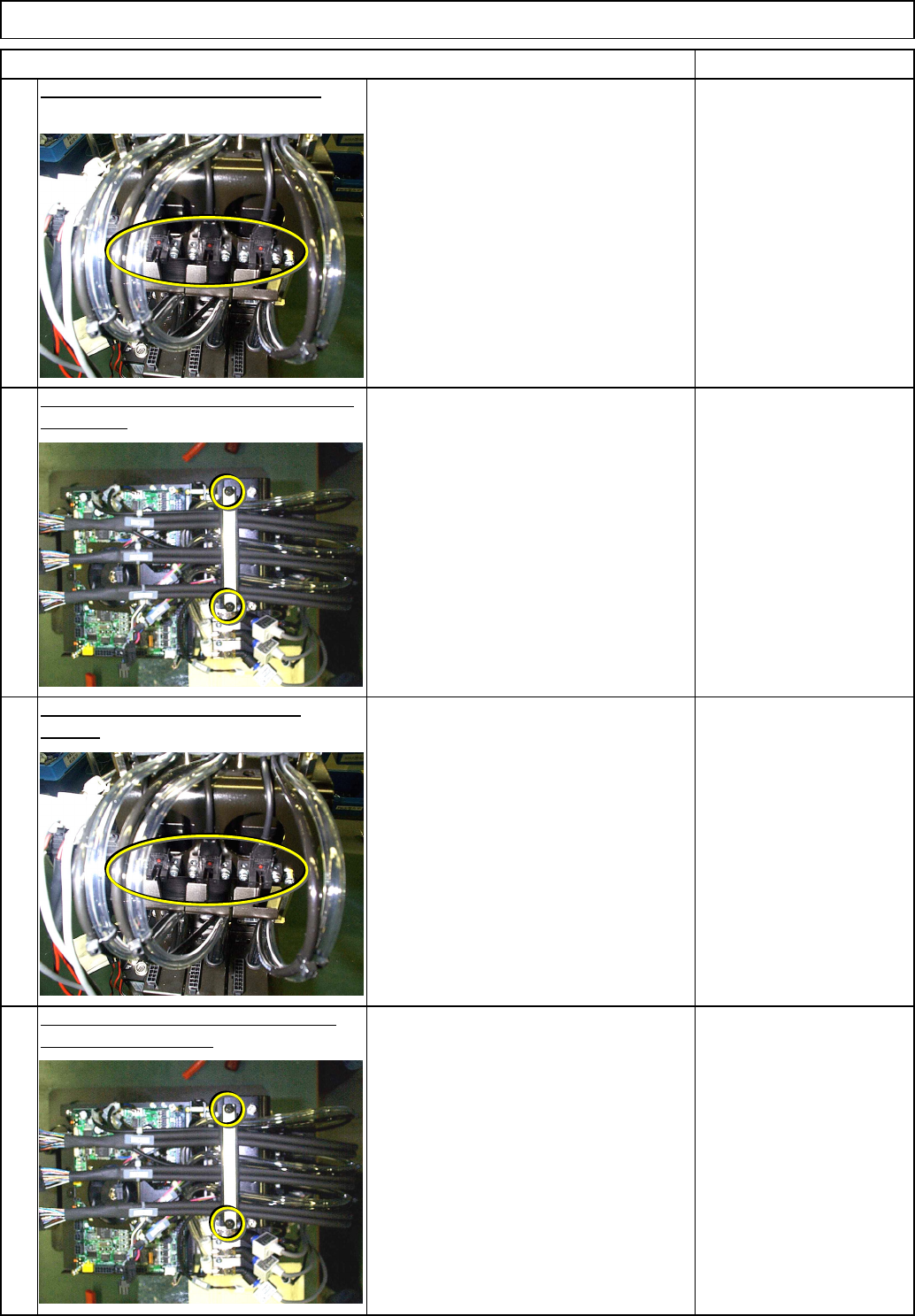
Remove the sensor holding screws.
Lightly tighten the sensor holding
7
6
Tools and Specifications
the sensor.
Allen key 2.5 mm
Screw M3 2 pcs.
Tools and Specifications
Raising the cable holding plate, remove
Raising the cable holding plate, place
8
the sensor in position.
EJM8A-E-SMA050508-A01-00
Page 5-5-8-3
Item Remarks
Machinery Part Replacement
Z Unit (3-nozzle type)
12
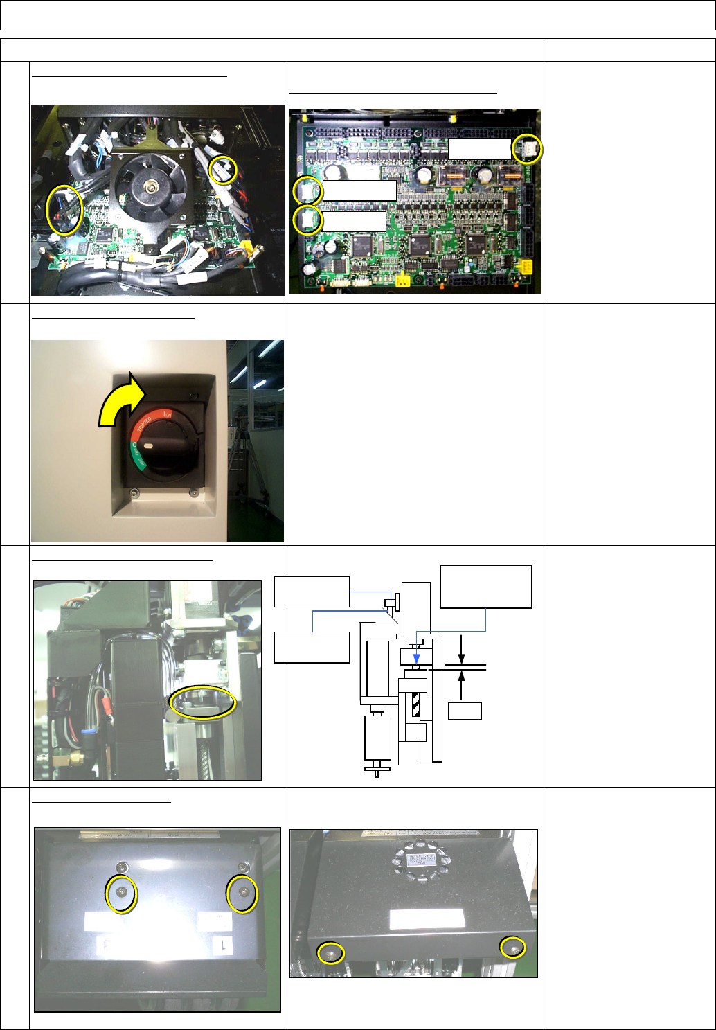
Put the cover back on.
Tools and Specifications
Phillips screwdriver #1
Phillips screwdriver #2
Screw M3 2 pcs.
M4 2 pcs.
11
Precisely position the sensor.
Tools and Specifications
Position the sensor so that
the rough origin sensor
turns ON when Gap from
the mechanical stopper to
the ball bearing is 2mm.
Tools and Specifications
Tools and Specifications
White connectors: Z origin sensor
Connect the sensor connectors.
9
10
Switch on the main power.
CN10: Z1
CN9: Z2
CN7:Z3
Z-axis rough
ori
g
in PH
Z-axis rough
ori
g
in do
g
Gap
Upper-limit
stopper
EJM8A-E-SMA050508-A01-00
Page 5-5-8-4