CM602all_EJM8AESM_Service Manual.pdf - 第689页
Machinery Part Replacement Remarks 12-Nozzle Head Teaching Item Press [Xyplane cal teach]. The jig is clamped in the Z direction. The AF head recognizes the dots on the jig. Then the AR head recognizes them. Press [Jig r…
Machinery Part Replacement
Remarks
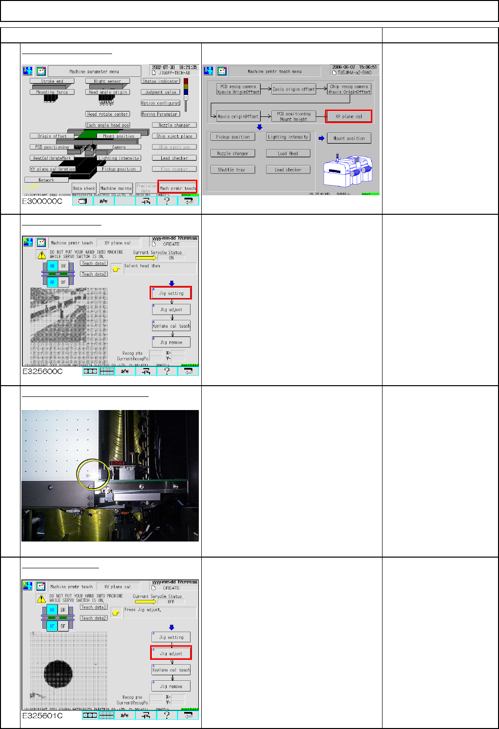
Press [XY plane cal].
Conveyor width is
adjusted to 460 mm
automatically.
Press [Jig setting].
The AF head moves away.
Place the jig on the conveyor.
Place the jig by hand, pressing the
reference-mark corner of the jig against
the fixed conveyor and the board
stopper.
Press [Jig adjust].
The jig is clamped in the Y direction.
(Option)
Check that the jig is
locked once clamped in
the Y direction.
12-Nozzle Head Teaching
Item
3
4
1
2
EJM8A-E-SMA051107-A01-00
Page 5-11-7-2
Machinery Part Replacement
Remarks
12-Nozzle Head Teaching
Item
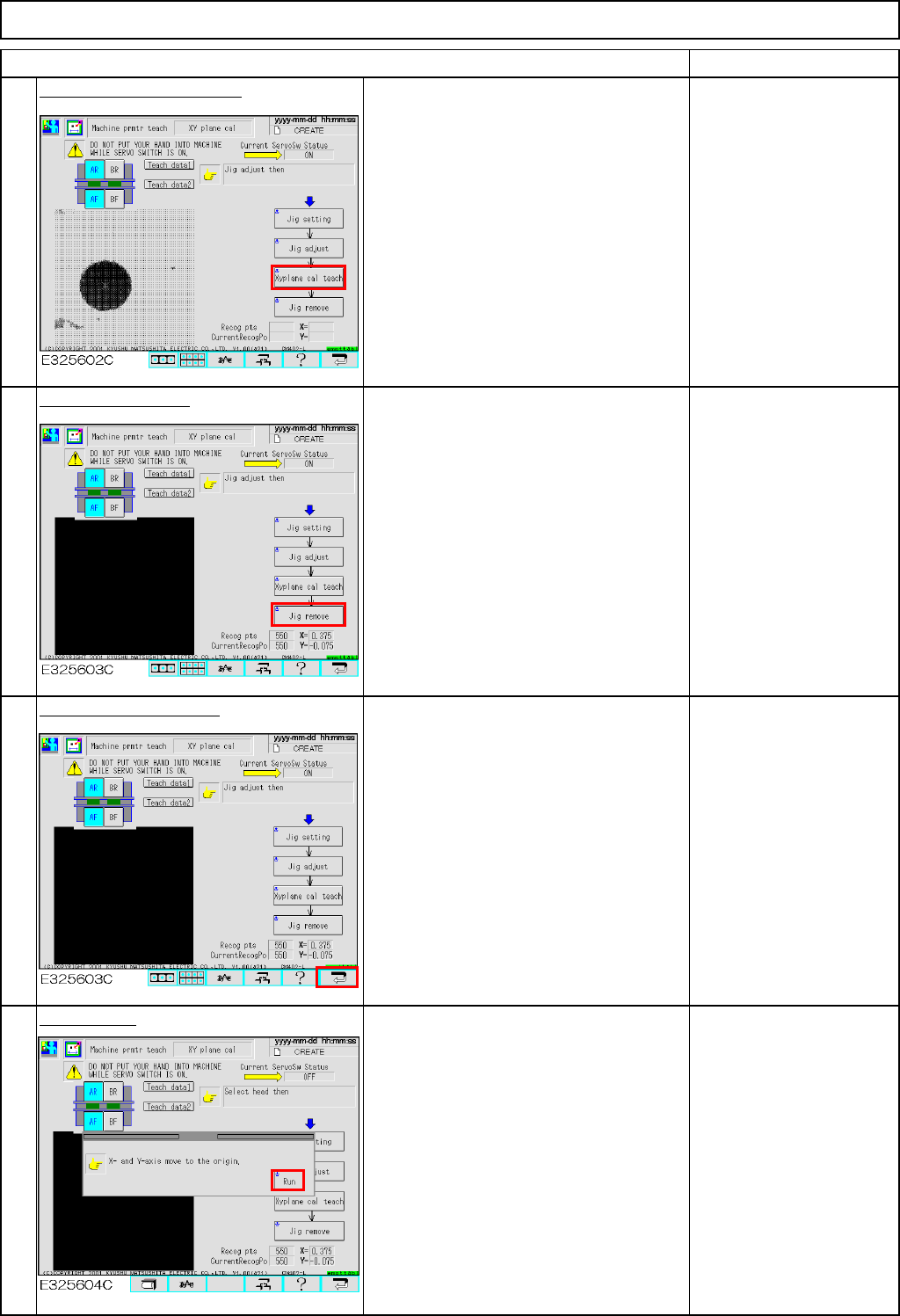
Press [Xyplane cal teach].
The jig is clamped in the Z direction.
The AF head recognizes the dots on the
jig. Then the AR head recognizes them.
Press [Jig remove].
Both AF and AR heads move away.
Once they finish moving away, remove
the jig.
Press the "Return" key.
Press [Run].
5
7
8
6
EJM8A-E-SMA051107-A01-00
Page 5-11-7-3
Machinery Part Replacement
Remarks
12-Nozzle Head Teaching
Item
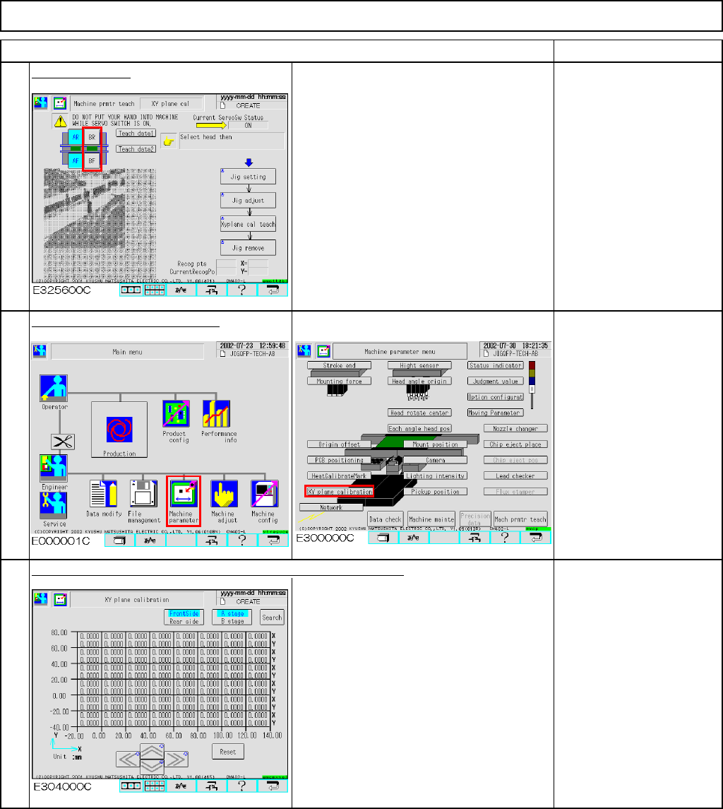
Change stages.
Select Stage B.
Carry out Steps 2 to 8 in the same way
as Stage A.
Check the data after teaching.
The offsets are entered automatically into the screen below:
Offset range:
X: -0.5 mm to +0.5 mm
Y: -0.5 mm to +0.5 mm
11
9
10
EJM8A-E-SMA051107-A01-00
Page 5-11-7-4